II-18
1.8
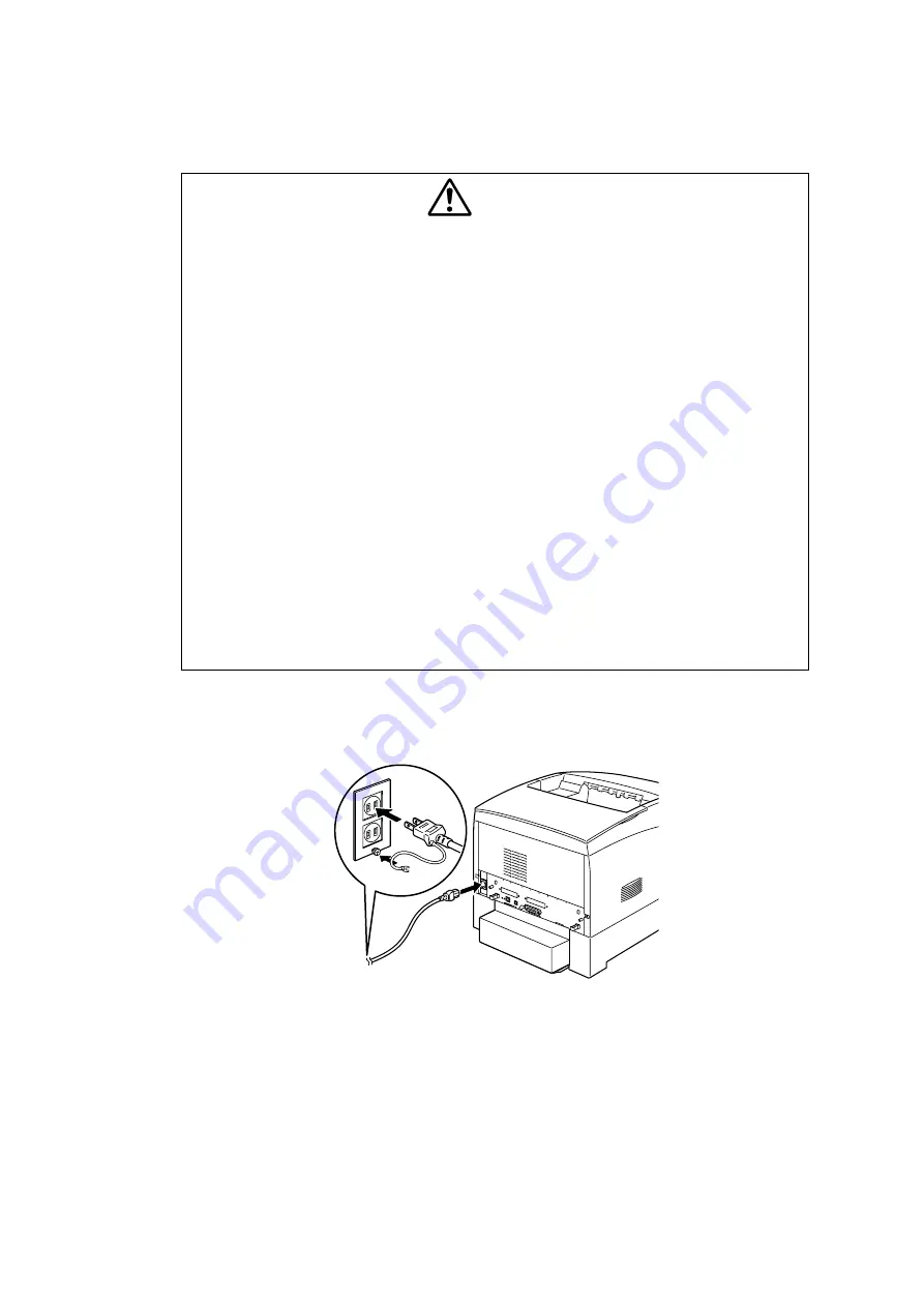
Connecting the Power Cable
Connect the power cable as explained below.
WARNING
Power specifications are listed below. The specifications that apply to your machine
depend on your machine configuration. Connect the power plug only to a properly rated
power outlet. Otherwise, it can cause fire or electric shocks. If in doubt, contact your
Customer Support Centre.
- Rated voltage 100V - Rated voltage 110V - Rated voltage 220-240 V
- Rated frequency 50/60Hz - Rated frequency 60Hz - Rated frequency 50/60Hz
Never use multi-plug adaptors to plug multiple power plugs in the same outlet. Be sure to
operate the machine on a sole-use receptacle. Multiple connectors can cause the outlet
to overheat and cause fire.
To prevent fire or electric shocks, follow the instruction below based on your machine
configuration. If in doubt, contact your dealer or authorized Brother service
representative.
- If your machine is a 220-240 V model, there is no need to attach a separate earth line
since the earth connection is incorporated in the power line. Plug it into a properly
rated outlet.
- If your machine is a 100 or 110 V model, use the green earth wire bundled with the
power cord, located at the rear of the machine.
The earth wire must be connected to one of the following conductors:
- Earth terminal of the specified power outlet
- A piece of copper buried in the earth 650 mm or deeper
- Earth terminal with Class D* earthing.
* Class D is the regulation for Japan only.
1)
Connect the power cable to the power cable connector on the rear of the printer.
If the power outlet has a ground terminal, connect the ground wire as well.
Fig.2-49
Summary of Contents for HL-4000CN
Page 22: ...CHAPTER I SPECIFICATIONS ...
Page 52: ...CHAPTER II INSTALLATION ...
Page 76: ...CHAPTER III STRUCTURE OF SYSTEM COMPONENTS ...
Page 129: ...CHAPTER IV ASSEMBLY DISASSEMBLY ...
Page 132: ...2 5 21 Roll ASSY IV 74 2 5 22 Cassette ASSY front IV 74 2 5 23 Holder retard IV 75 ...
Page 208: ...CHAPTER V TROUBLESHOOTING ...
Page 281: ...V 71 9 4 Straightness Fig 5 13 9 5 Magnification Error Fig 5 14 9 6 Registration Fig 5 15 ...
Page 282: ...V 72 9 7 Guaranteed Printing Area Fig 5 16 ...
Page 295: ...CHAPTER VI 5 06 ...
Page 336: ...CHAPTER VII 3 8 3 211 725 2 7 216 ...
Page 341: ...VII 4 P J LAYOUT DIAGRAM 2 1 IOT Top ...
Page 342: ...VII 5 2 2 IOT Front RH ...
Page 343: ...VII 6 2 3 MCU and HVPS PWB ESS PWB ...
Page 344: ...VII 7 2 4 Tray1 ...
Page 345: ...VII 8 2 5 2 Tray Module ...


