background image

sss

 1143  

page

 6

D

isassembling


The

 C

arTriDge

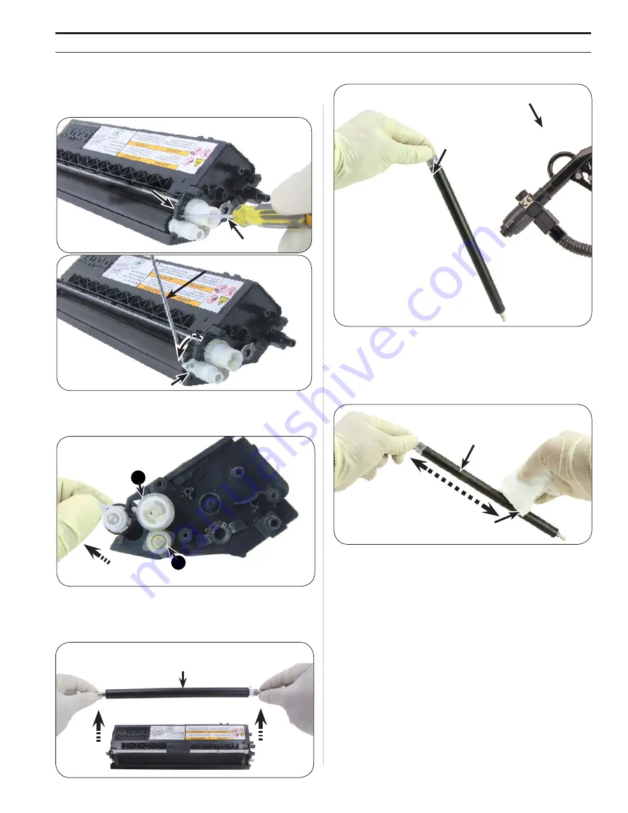
7.  Place a slotted screwdriver into the opening directly in front of the 

developer roller stabilizer. Gently press on the stabilizer to release 

(Figure 7a). Rotate the developer roller stabilizer out and down as 

shown in Figure 7b.

Developer Roller 

Stabilizer 

Figure 7a

Slotted

Screwdriver

Figure 7b

Developer Roller Stabilizer 

Slotted Screwdriver


8.  Lift the developer roller slightly to remove the drive gear. Remove the 

drive gear and toner adder roller gear in the order shown in Figure 8.

Figure 8

Toner Adder Roller Gear

Drive Gear

2

1


9.  Remove the developer roller by grasping the ends of the roller and 

pulling out and away from the cartridge as shown in  

Figure 9.

Figure 9

Developer Roller

10.  Blow with dry, filtered, ionized, compressed air (Figure 10). 

Figure 10

Air Gun

Developer Roller

11.  Using a lint-free cloth dampened with 91-99% isopropyl alcohol, 

gently clean the developer roller using end-to-end strokes. Using 

another lint-free cloth, dampened with de-ionized water, gently wipe 

the developer roller as shown in Figure 11. Blow with dry, filtered, 

ionized, compressed air.

Figure 11

Lint-Free Cloth

Developer Roller

Summary of Contents for DR-310CL

Page 1: ...200 DCP L8400 MFC L8600 8650 8850 9550 Brother TN 310BK TN 310C TN 310M TN 310Y TN 315BK TN 315C TN 315M TN 315Y and DR 310CL TN 331BK TN 331C TN 331M TN 331Y TN 336BK TN 336C TN 336M TN 336Y SSS 1143 Tools Supplies 2 Wirelines 3 Disassembling the Cartridge 5 Assembling the Cartridge 9 Resetting the Flag Gear 12 Disassembling the Drum Unit 13 Installing the Drums 15 Assembling the Drum Unit 17 Res...

Page 2: ...ubricant LUBE 44 Toner Pour Spout for Toner Bottle TPS Toner Cloth TCLOTH Safety Glasses De Ionized Water Angle Blade Knife Tool ABKTOOL Conductive Lubricant CONCLUBE Lint Free Swab LFSWAB Dry Filtered Ionized Compressed Air Small Slotted Screwdriver Phillips Screwdriver Safety Glasses Toner Vacuum TONERVAC115 or TONERVAC220 Toner Cloth TCLOTH 91 99 Isopropyl Alcohol De Ionized Water Cartridge Lub...

Page 3: ...per Roller Stabilizer E Clip Doctor Blade Sealing Felt Flag Gear Flag Gear Spring Agitator Gear Idler Gear Contact Side Support Bearing Contact Side Support Bearing Spring Adder Roller Drive Gear Drive Side Contact Side Static Control Components Inc All rights reserved worldwide The stylized S Static Control and Odyssey are registered trademarks of Static Control Components Inc All other brand or ...

Page 4: ...Contact Side End Plate Drive Side End Plate Drum Unit Retaining Springs Static Control Components Inc All rights reserved worldwide The stylized S Static Control and Odyssey are registered trademarks of Static Control Components Inc All other brand or product names are trademarks or registered trademarks of their respective companies ...

Page 5: ...ps screwdriver remove the screw on the contact side end plate as shown in Figure 1 Figure 1 Screw End Plate Contact Side Phillips Screwdriver 2 Using a slotted screwdriver pry under the contact side support bearing as shown to remove support bearing and spring Figure 2 Figure 2 Support Bearing Slotted Screw driver 3 Locate the locking tab under the contact side end plate and release the tab using ...

Page 6: ...er adder roller gear in the order shown in Figure 8 Figure 8 Toner Adder Roller Gear Drive Gear 2 1 9 Remove the developer roller by grasping the ends of the roller and pulling out and away from the cartridge as shown in Figure 9 Figure 9 Developer Roller 10 Blow with dry filtered ionized compressed air Figure 10 Figure 10 Air Gun Developer Roller 11 Using a lint free cloth dampened with 91 99 iso...

Page 7: ... the doctor blade from the cartridge Figure 14 Figure 14 Doctor Blade Note Use dry filtered ionized compressed air to loosen any excess toner or additive 15 Using a lint free cloth dampened with 91 99 isopropyl alcohol gently clean the black material on the doctor blade using back and forth strokes from end to end as shown in Figure 15 Using another lint free cloth dampened with de ionized water g...

Page 8: ...g the molded plastic will prevent damage to the hopper cap 19 Clean the hopper with dry filtered ionized compressed air Figure 19 Figure 19 Toner Hopper Air Gun 20 Use a slotted screwdriver to gently clean any remaining toner additive from the developer roller end felts Figure 20 Fluff felts then blow with dry filtered ionized compressed air Figure 20 Toner Hopper Felt Slotted Screwdriver Note If ...

Page 9: ...e cartridge Figures 23a and 23b Figure 23a Doctor Blade Phillips Screwdriver Figure 23b Cartridge Screw Doctor Blade Screw Note Doctor blade screws are different than the cartridge screws Figure 23b 3 Install the toner adder roller gear and then the drive gear as shown in Figure 24 Figure 24 Drive Gear Toner Adder Roller Gear 1 2 4 Holding the ends of the developer roller place the developer rolle...

Page 10: ... 6 On the drive side install the gears and spring in the order shown in Figure 27a Install the flag gear spring as shown in Figure 27b Figure 27a Idler Gear Agitator Gear Flag Gear Flag Gear Spring 3 2 1 4 Figure 27b Flag Gear Spring Note See page 14 for instructions about resetting the flag gear 7 Place the drive side end plate onto the cartridge and secure with three screws Figures 28a and 28b F...

Page 11: ...SSS 1143 page 11 Assembling the Cartridge 9 Reinstall hopper cap Figure 30 Figure 31 Hopper Cap Note Replace the OEM hopper cap with a replacement if the OEM hopper cap is damaged ...

Page 12: ...ce the location of the flag gear tab Figure 33 Flag Gear Flag Gear Tab Cartridge Tab 2 Put the long arm of the spring over the flag gear and the short arm of the spring under the cartridge tab as shown in Figure 34a Final assembly is shown in Figures 34a and 34b Note the gear tab and cartridge tab Tabs are now slightly separated due to spring tension This is normal Spent position Figure 34c Figure...

Page 13: ...d screwdriver remove the white drum bearings on the drive side of the drum unit and set aside Figures 37a and 37b Figure 37a Slotted Screwdriver Drive Side Drum Bearing Drive Side Figure 37b Drive Side Drum Bearings Drive Side 4 Lift the drum drive gear up to disengage from the cleaning roller drive gear Figure 38a Use a slotted screwdriver to push the contact side of the drum towards the drive si...

Page 14: ...d from the contact side of the drum unit 7 Lift the drum out of the drum unit contact side first Figure 41 Figure 41 Drum 8 Remove the white contact side drum bearing from the end of the drum Figure 42a and remove any residual lubricant from the contact bearing with a lint free cloth Figure 42b Figure 42a Drum Figure 42b Contact Side Drum Bearing 9 After all four drums have been removed clean the ...

Page 15: ...rum Note Ensure the small transparent plastic wiper tabs are positioned on top of all the drums 12 Rotate the drum contact bearing until the larger locking tab is positioned at the top and set the contact side of the drum into the drum unit Figures 45a 45b and 45c Figure 45a Drum Figure 45b Drum Figure 45c Large Locking Tab Installing the Drums Note The following steps should be completed for each...

Page 16: ...ng locks will lock into place with a click sound when installed properly 14 Install the retaining spring Figure 47 Figure 47 Spring 15 Apply cartridge lubricant using a lint free swab then install the white drive side drum bearings Figures 48a and 48b Figure 48a Drive Side Drum Bearing Figure 48b Drive Side Drum Bearing Installing the Drum Lint Free Swab ...

Page 17: ...e drum unit with the corresponding holes in the end plates Figures 50a and 50b Figure 50a Figure 50b 3 Rotate the end plates up and secure each end plate with 5 screws Figures 51a 51b and 51c Figure 51a Drive Side End Plate Figure 51b Drive Side End Plate Phillips Screwdriver Screws Figure 51c Contact Side End Plate Phillips Screwdriver Screws Assembling the Drum Unit Holes Tabs Holes Tabs ...

Page 18: ...e Press OK 3 Press or to navigate Drum Unit Press OK 4 Press or to reset the drum unit counter OPTION 2 1 Press the Go button and button simultaneously 2 The Reset Menu will appear 3 Press OK Press to reset the drum counter Note When replacing the drum unit with a new drum unit reset the drum counter by completing one of the following options ...

Page 19: ... from the OEM it is essential to follow Static Control s remanufacturing instructions exactly as directed Static Control is dedicated to informing customers of the latest innovations in training and knowledge Access to these instructions our technical support staff and View on Demand Webinars is available to all customers in good standing ELECTROPHOTOGRAPHICALLY MATCHED COMPONENTS We provide these...

Reviews: