App. 1-44
Confidential
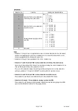
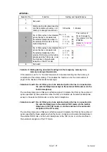
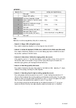
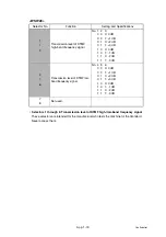
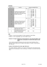
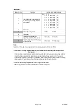
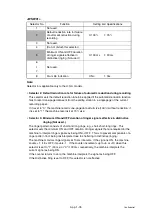
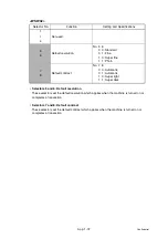
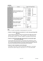
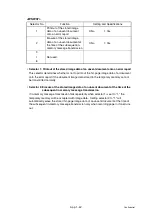
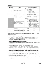
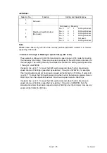
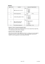
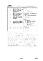
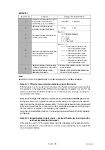
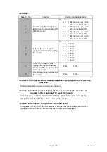
<WSW39>
Note:
WSW39 takes effect only when the V.34 mode is permitted (WSW19, selector 7) in models
supporting V.34 mode. For the transmission speed setting in other modes, refer to WSW19.
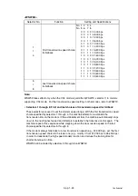
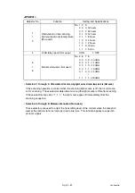
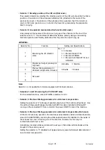
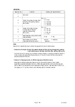
• Selectors 1 through 8: First and last choices of transmission speed for fallback
These selectors are used to set the modem speed range. With the first transmission speed
choice specified by selectors 1 through 4, the machine attempts to establish the
transmission link via the modem. If the establishment fails, the machine automatically steps
down to the next highest speed and attempts to establish the transmission link again. The
machine repeats this sequence while stepping down the transmission speed to the last
choice specified by selectors 5 through 8.
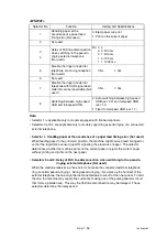
If the modem always falls back to a low transmission speed (e.g., 24,000 bps), set the first
transmission speed choice to the lower one (e.g., modify it from 31,200 bps to 26,400 bps)
in order to deactivate the high-speed modem function and reduce the training time for
shorter transmission time.
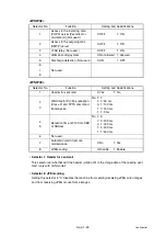
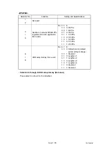
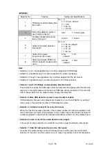
WSW39 will be limited by selectors 3 through 8 on WSW40.
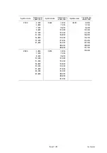
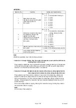
Selector No.
Function
Setting and Specifications
1
I
4
First transmission speed choice
for fallback
No. 1 2 3 4
No. 5 6 7 8
0 0 0 0: 2,400 bps
0 0 0 1: 4,800 bps
0 0 1 0: 7,200 bps
0 0 1 1: 9,600 bps
0 1 0 0: 12,000 bps
0 1 0 1: 14,400 bps
0 1 1 0: 16,800 bps
0 1 1 1: 19,200 bps
1 0 0 0: 21,600 bps
1 0 0 1: 24,000 bps
1 0 1 0: 26,400 bps
1 0 1 1: 28,800 bps
1 1 0 0: 31,200 bps
1 1 0 1: 33,600 bps
1 1 1 0: 33,600 bps
1 1 1 1: 33,600 bps
5
I
8
Last transmission speed choice
for fallback
Summary of Contents for DCP-7030
Page 201: ...5 5 Confidential Print sample Fig 5 1 ...
Page 226: ...5 30 Confidential Location of fans Fig 5 13 Fan motor 60 unit Right side ...
Page 234: ...6 2 Confidential LVPS PCB Circuit Diagram 100V ...
Page 235: ...6 3 Confidential LVPS PCB Circuit Diagram 200V ...
Page 239: ...6 7 Confidential Wiring Diagram ...

