


II-1
1.
INSTALLING THE UPDATE DATA TO THE
FACSIMILE MACHINE
If you want to update the current program stored in the flash ROM of the main PCB to the newer
version or after you replace the main PCB, install the update program onto the flash ROM.
The program installation requires a PC/AT-compatible computer (which is capable of
running MS-DOS or its compatible OS).
Connecting the facsimile machine to your computer
(1) Make sure that your computer is turned off.
(2) Make sure that the machine's power cord is unplugged from a wall socket. (If the machine has
a power ON/OFF switch, make sure that the switch is turned off.)
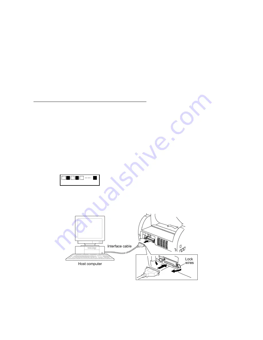
(3) Connect the parallel interface cable to the parallel port on the back of the machine and secure
it with the lock wires.
(4) Connect the other end of the interface cable to the printer port of your computer and secure it
with the two screws.
(5) While pressing the
5
key on the machine's control panel, plug the machine's power cord into a
wall socket (or turn on the power ON/OFF switch if the machine has the switch).
(6) Check to see that the following pattern displays on the LCD. If it does not display, go back to
step (2) above.
←
1st row
←
2nd row
(7) Turn on your computer.
Summary of Contents for DCP-1400
Page 1: ...MULTI FUNCTION CENTER SERVICE MANUAL MODEL MFC9800 MFC9700 DCP1400 MFC9880 MFC9860 MFC9760 ...
Page 5: ...CHAPTER I GENERAL DESCRIPTION ...
Page 24: ...CHAPTER II INSTALLATION ...
Page 29: ...CHAPTER III THEORY OF OPERATION ...
Page 31: ...III 1 1 OVERVIEW Provided on models supporting facsimile function ...
Page 35: ...III 5 2 2 Laser Printing Mechanism 2 2 1 Paper pick up and registration mechanism ...
Page 44: ...CHAPTER IV DISASSEMBLY REASSEMBLY AND LUBRICATION ...
Page 106: ...IV 60 Setting up the main PCB after replacement ...
Page 116: ...IV 70 ...
Page 118: ...IV 72 2 Scanner mount ...
Page 119: ...IV 73 3 Drive gear ASSY ...
Page 120: ...IV 74 4 Paper cassette ...
Page 121: ...CHAPTER V MAINTENANCE MODE ...
Page 129: ...V 7 Scanning Compensation Data List ...
Page 137: ...V 14 1 MFC9760 Key Button Entry Order 2 ...
Page 145: ...CHAPTER VI ERROR INDICATION AND TROUBLESHOOTING ...
Page 174: ...VI 28 Location of High voltage Contacts and Grounding Contacts ...
Page 175: ...VI 29 ...
Page 176: ...MFC9800 MFC9700 DCP1400 MFC9880 MFC9860 MFC9760 Appendix 1 EEPROM Customizing Codes ...
Page 179: ...MFC9800 MFC9700 DCP1400 MFC9880 MFC9860 MFC9760 Appendix 2 Firmware Switches WSW ...
Page 229: ...A Main PCB 1 6 MFC9800 MFC9880 MFC9860 MFC9760 ...
Page 230: ...A Main PCB 2 6 MFC9800 MFC9880 MFC9860 MFC9760 ...
Page 231: ...A Main PCB 3 6 MFC9800 MFC9880 MFC9860 MFC9760 ...
Page 232: ...A Main PCB 4 6 MFC9800 MFC9880 MFC9860 MFC9760 ...
Page 233: ...A Main PCB 5 6 MFC9800 MFC9880 MFC9860 MFC9760 ...
Page 234: ...A Main PCB 6 6 MFC9800 MFC9880 MFC9860 MFC9760 ...
Page 235: ...A Main PCB 1 6 MFC9700 DCP1400 ...
Page 236: ...A Main PCB 2 6 MFC9700 DCP1400 ...
Page 237: ...A Main PCB 3 6 MFC9700 DCP1400 ...
Page 238: ...A Main PCB 4 6 MFC9700 DCP1400 ...
Page 239: ...A Main PCB 5 6 MFC9700 DCP1400 ...
Page 240: ...A Main PCB 6 6 MFC9700 DCP1400 ...
Page 241: ...B Relay PCB ...
Page 242: ...C Engine PCB ...
Page 243: ...D NCU PCB U S A Canada ...
Page 245: ...D NCU PCB Asia Oceania 1 2 ...
Page 247: ...E Control Panel PCB MFC9800 MFC9860 MFC9880 ...
Page 248: ...E Control Panel PCB 1 2 DCP1400 MFC9760 ...
Page 249: ...E Control Panel PCB 2 2 DCP1400 MFC9760 ...
Page 250: ...E Control Panel PCB 1 2 MFC9700 ...
Page 251: ...E Control Panel PCB 2 2 MFC9700 ...
Page 252: ...F Power Supply PCB 100 120V Low voltage power supply ...
Page 253: ...F Power Supply PCB 200 240V Low voltage power supply ...
Page 254: ...F Power Supply PCB High voltage power supply ...


