Brother BAS-342G PS Instruction Manual Download Page 26

4. INSTALLATION 


17 

BAS-342G PS

4-18. Lubrication [13] 

   CAUTION 

Do not connect the power cord until lubrication is complete. 
If the foot switch is depressed by mistake, the sewing machine might start operating and injury could result. 

Be sure to wear protective goggles and gloves when handling the lubricating oil and grease, so that they do not get into 
your eyes or onto your skin. If the oil and grease get into your eyes or onto your skin, inflammation can result. 
Furthermore, do not drink or eat the lubricating oil or grease. They may cause diarrhea or vomiting. 
Keep the oil out of the reach of children.


  The sewing machine should always be lubricated and the oil 

supply replenished before it is used for the first time, and 
also after long periods of non-use. 

 Use only the lubricating oil <JX Nippon Oil & Energy 

Corporation Sewing Lube 10N; VG10> specified by Brother.


*  If this type of lubricating oil is difficult to obtain, the recommended 

oil to use is <Exxon Mobil Essotex SM10; VG10>. 

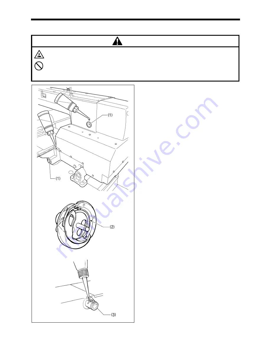
1.  Fill the arm oil tank and the bed oil tank with oil.


NOTE:


Be sure to add more oil when the oil level drops down 
to about one-third full in the oil gauge window (1). If the 
oil drops below the one-third full level in the oil gauge 
window (1), there is the danger that the sewing 
machine may seize during operation.


2. Remove the bobbin case and add 2-3 drops of oil to the 

rotary hook race (2). 


3. If using the needle cooler (3), fill it with silicon oil (100 

mm

2

/s). 

(Refer to "5-3. Threading the upper thread" for details on 
using the needle cooler (3).) 


2752B 
2753B 

3986M 

Summary of Contents for BAS-342G PS

Page 1: ... 342G PS Please read this manual before using the machine Please keep this manual within easy reach for quick reference DIRECT DRIVE PROGRAMMABLE ELECTRONIC PATTERN SEWER PERFECT STITCH INSTRUCTION MANUAL ...

Page 2: ...ial sewing machines it is normal to carry out work while positioned directly in front of moving parts such as the needle and thread take up lever and consequently there is always a danger of injury that can be caused by these parts Follow the instructions from training personnel and instructors regarding safe and correct operation before operating the machine so that you will know how to use it co...

Page 3: ...tuations where failure to follow the instructions may result in minor or moderate injury IMPORTANT The instructions which follow this term indicate situations where failure to follow the instructions may result in physical damage to equipment and surroundings or result in problems with equipment operation Symbols This symbol indicates something that you should be careful of The picture inside the ...

Page 4: ...your Brother dealer or a qualified electrician for any electrical work that may need to be done The sewing machine weighs approximately 160 kg Use equipment such as a crane or hoist when installing the machine head and adjusting the height of the table If you try to lift the machine head yourself it may cause injuries such as back injury Do not connect the power cord until installation is complete...

Page 5: ...ch of children Maintenance and inspection Maintenance and inspection of the sewing machine should only be carried out by a qualified technician Ask your Brother dealer or a qualified electrician to carry out any maintenance and inspection of the electrical system Turn off the power switch and disconnect the power cord before carrying out the following operations If the foot switch is depressed by ...

Page 6: ...er 1 2 3 4 5 Be careful to avoid getting hands caught in sliding parts Be sure to connect the ground If the ground connection is not secure you run a high risk of receiving a serious electric shock and problems with correct operation may also occur Direction of operation Safety devices Devices such as eye guard finger guard thread take up cover motor cover X motor cover tension release solenoid co...

Page 7: ...e up cover Finger guard Inside cover R Outside cover Fixed cover Eye guard Middle cover Rear cover Rear cover Tension release solenoid cover Motor cover Rear cover Inside cover L Outside cover Fixed cover Middle cover X motor cover ...

Page 8: ...read 22 5 5 Installing the bobbin case 23 5 6 Thread tension 24 5 6 1 Lower thread tension 24 5 6 2 Upper thread tension 24 5 7 Home position detection 25 5 8 Setting 2 step operation for the work clamp 26 6 USING THE OPERATION PANEL BASIC OPERATIONS 27 6 1 Name and function of each operation panel item 27 6 2 Loading sewing data 29 6 3 Setting the program number 29 6 4 Setting the X scale and Y s...

Page 9: ...bar height 56 11 4 Adjusting the needle bar lift amount 57 11 5 Adjusting the driver needle guard 57 11 6 Adjusting the needle clearance 58 11 7 Adjusting the inner rotary hook and hook stopper overlap 58 11 8 Adjusting the rotary hook lubrication amount 58 11 9 Adjusting the position of the movable knife 59 11 10 Replacing the movable and fixed knives 62 11 10 1 Installing the feed plate 63 11 11...

Page 10: ... devices 2 CF slot 12 Finger guard 3 Power switch 13 Eye guard 4 Work clamp switch 14 Thread take up cover 5 Start switch 15 Motor cover 6 Control box 7 Solenoid valve 8 Operation panel 9 Thread wiper switch 10 Pulley 11 Cotton stand CFTM is a trademark of SanDisk Corporation 2741B ...

Page 11: ...amount 19 5 mm Intermittent stroke 2 4 5 mm 4 5 10 mm or 0 Default setting 3 mm Rotary hook Double capacity rotary hook Wiper device Standard equipment Thread trimmer Standard equipment Data storage method Internal memory Flash memory CF card 32 MB 2 GB 3 5 floppy disk 2HD 1 44MB 2DD 2 User programs 50 Cycle programs 9 Motor 550 W AC servo motor Weights Machine head approx 160 kg operation panel a...

Page 12: ...d be strong enough to bear the weight and vibration of the sewing machine If using casters use ones which can bear the total weight of sewing machine and table Check that the control box is at least 10 mm away from the leg If the control box and the leg are too close together it may result in incorrect sewing machine operation 4053M ...

Page 13: ...ning it to its original position In addition do not subject the machine head to extra force while it is tilted back If this is not observed the machine head may become unbalanced and fall down and serious injury or damage to the sewing machine may result All cords should be secured at least 25 mm away from any moving parts Furthermore do not excessively bend the cords or secure them too firmly sta...

Page 14: ...X control box for BAS 342G sewing machines If the sewing machine is installed to the table tilt back the machine head Refer to 4 5 Tilting back and returning the machine head 1 Control box 2 Bolts 4 pcs 3 Plain washers 4 pcs 4 Spring washers 4 pcs 5 Nuts 8 pcs NOTE Check that the control box 1 is at least 10 mm away from the leg If the control box 1 and the leg are too close together it may result...

Page 15: ...st to install the sewing machine Be careful of the following when lowering the machine head onto the table Do not let any cords get clamped between the machine head and the table Do not place the machine head cushion c on top of the oil pan a or the support lever base b Do not let the side d of the safety switch lever touch the support lever base b 1 Rubber bushes 2 pcs 2 Hinge holders 2 pcs 3 Pla...

Page 16: ... the machine head with both hands when tilting it back or returning it to its original position In addition do not subject the machine head to extra force while it is tilted back If this is not observed the machine head may become unbalanced and fall down and serious injury or damage to the sewing machine may result Always be sure to engage the stopper of the support lever 1 when tilting back the ...

Page 17: ... holders L and R 5 Spacer 6 Bolt 7 Nut 8 Gas spring 9 Shaft collars 2 pcs 10 Gas spring shaft D 11 Plain washers 2 pcs 12 Retaining rings E 2 pcs 13 Bolts 4 pcs 14 Plain washers 4 pcs 15 Spring washers 4 pcs 16 Nuts 4 pcs 17 Gas spring shaft U 18 Set screw After installing the gas spring 8 gently return the machine head to its original position Refer to 4 5 Tilting back and returning the machine h...

Page 18: ...ness of cushion B 5 is about 1 mm 8 Rubber seat 9 Operation panel stand 10 Operation panel Pass the cords of the operation panel 10 through the operation panel stand 9 and under the table 11 Bolts 3 pcs 12 Bolt If the sewing machine was already installed to the table when it was delivered 1 Operation panel 2 Bolts 3 pcs Pass the cords of the operation panel 1 through the operation panel stand 3 an...

Page 19: ...table 4 9 Connecting the air tubes 4 4 10 Installing the air hose 5 1 Close the cock 1 2 Turn the nut 3 at the end of the air hose 2 and connect it to the valve 4 3 Open the cock at the compressor Check that no air is leaking from the connection of the valve 4 and air hose 2 4 Open the cock 1 The meter pointer will turn clockwise NOTE Turn the cock 1 gently to open it 5 Adjust the air pressure Ref...

Page 20: ...ightened the lowering speed becomes slower When it is loosened the lowering speed becomes faster Reference adjustments Upper knob Fully tighten Valve 1 Lower knob Fully tighten and then loosen by 8 turns Upper knob Fully tighten and then loosen by 5 turns Valve 2 Lower knob Fully tighten You can operate the work clamp when the power is turned off by pressing the manual buttons 1 Adjusting the spee...

Page 21: ...s into place Secure the cables with cable ties and cord clamps while being careful not to pull on the connector Be sure to make the ground connection Refer to 4 14 Connecting the ground wire Connector Connection location on main P C board Cord clamp X pulse motor encoder 5 pin white P20 X ENC 3 Y pulse motor encoder 5 pin blue P4 Y ENC 3 Intermittent presser foot pulse motor encoder 5 pin black P5...

Page 22: ...tor Connection location on PMD P C board Cable tie Work clamp pulse motor 4 pin black P3 PPM 5 6 Thread trimmer solenoid 6 pin P6 SOL1 5 6 Tension release solenoid 4 pin P7 SOL2 5 6 Y pulse motor 4 pin blue P8 YPM 5 6 X pulse motor 4 pin white P10 XPM 5 6 Removing Press the tab Securing 2568B NOTE Route the X Y and work clamp pulse motor harnesses so that they do not touch the PMD P C Be sure to m...

Page 23: ... risk of receiving a serious electric shock and problems with correct operation may also occur 1 Ground wire from upper shaft motor harness 2 Ground wire from the machine head 3 Ground wire from operation panel 4 Ground wires from two pedal foot switch harnesses 2 wires NOTE Make sure that the ground connections are secure in order to ensure safety 2750B ...

Page 24: ... head 2 Check that none of the cords are being pulled 3 Return the machine head to its original position 4 Close the cord presser plate 3 in the direction of the arrow and secure it by tightening the two screws 4 NOTE Close the cord presser plate 3 securely so that no foreign objects insects or small animals can get inside the control box 5 Secure the cover of the control box by tightening the eig...

Page 25: ...ult 1 Screw loosen 2 Eye guard tilt forward 3 Eye guard assembly 4 Plain washers 2 pcs 5 Screws 2 pcs After installing the eye guard assembly 3 return the eye guard 2 to its original angle and then tighten the screw 1 to secure it in place 4 17 Installing the cotton stand 12 1 Cotton stand NOTE Fit the washer 2 and then securely tighten the nut 3 so that the cotton stand does not move 3983M 2367B ...

Page 26: ...ply replenished before it is used for the first time and also after long periods of non use Use only the lubricating oil JX Nippon Oil Energy Corporation Sewing Lube 10N VG10 specified by Brother If this type of lubricating oil is difficult to obtain the recommended oil to use is Exxon Mobil Essotex SM10 VG10 1 Fill the arm oil tank and the bed oil tank with oil NOTE Be sure to add more oil when t...

Page 27: ...t may cause problems with correct operation 4 20 Checking the safety switch 15 1 If the machine head is tilted back gently return it to its original position Refer to 4 5 Tilting back and returning the machine head 2 Turn on the power switch 3 Check that no error numbers are displayed on the operation panel If error E050 E051 or E055 is displayed If the safety switch 1 is not turned on error E050 ...

Page 28: ... far as it will go so with the hollow 3 facing to the front and so that it s angle matches the angle of reference line 4 and then securely tighten the set screw 1 Figure B If the installation angle of the needle has been changed be sure to readjust the needle clearance Refer to 11 6 Adjusting the needle clearance 5 2 Operating the 2 pedal foot switch When the work clamp switch left side is depress...

Page 29: ...he thread take up 3 to its highest position before threading the upper thread This will make threading easier and it will prevent the thread from coming out at the sewing start When threading the thread through the needle allow a distance of approximately 45 mm between the needle hole and the end of the thread If the trailing length of the thread is too long it may cause the thread to become tangl...

Page 30: ...ser foot will be lowered The tension discs will open 3 Threading the thread When 5 minutes have passed the buzzer will sound and the tension discs will close When memory switch No 564 is set to 2 the buzzer will sound after one minute has elapsed and the tension discs will close 4 Ending threading mode THREAD CLAMP indicator switches off Press the THREAD CLAMP key The work clamp and the intermitte...

Page 31: ...SION WIND key 5 after the machine starts operating and keep depressing the start switch 4 until the lower thread stops being wound onto the bobbin If you release the start switch 4 while this operation is in progress hold down the TENSION WIND key 5 and then depress the start switch 4 to restart winding of the thread 9 Once winding of the set amount of lower thread 80 90 of the bobbin capacity is ...

Page 32: ...hread winds to the right insert the bobbin into the bobbin case 3 Pass the thread through the thread slot 2 pass it underneath the spring 3 and then pass it through the thread guide 4 leaving a trailing out length of about 35 mm 4 Hold the latch on the bobbin case and insert the bobbin case into the rotary hook 5 Clamp the lower thread in the thread hold spring 5 6 Use the threading bar 6 to pass ...

Page 33: ...Needle DP x 17 19 Normal sewing speed 2 000 sti min 5 6 1 Lower thread tension Adjust the lower thread tension by turning the adjusting screw 1 5 6 2 Upper thread tension 1 Turn the tension nut 1 main tension to adjust the tension as appropriate for the material being sewn 2 Use the tension nut 2 sub tension to adjust the upper thread trailing length to about 45 mm 2573B Weaker Stronger Weaker Str...

Page 34: ...play 5 After this the program number will flash in the PROGRAM No display 4 2 Depress the work clamp switch 6 to lower the work clamp and then depress the start switch 7 After home position detection is carried out the work clamp will move to the sewing start position and then it will rise For programs with a large number of stitches the buzzer will sound after the home position is detected and th...

Page 35: ...work clamp switch 4 to the 1st step and check the intermediate position for the work clamp 5 Depress the work clamp switch 4 to the 2nd step to fully lower the work clamp 2 step work clamp operation is enabled when memory switch No 002 is set to 1 Do not set memory switch No 002 to 2 To return the work clamp to one step operation 1 Set memory switch No 002 to 0 Refer to 7 2 Setting memory switches...

Page 36: ...en an error occurs 3 RESET key Used to reset errors 4 TEST key Used to start test mode 5 TEST indicator Illuminates when the TEST key 4 has been pressed 6 THREAD CLAMP key Used to start threading mode or work clamp height setting mode 7 THREAD CLAMP indicator Illuminates when the THREAD CLAMP key 6 has been pressed 8 TENSION WIND key Used to wind the lower thread 9 TENSION WIND indicator Used when...

Page 37: ...ct a menu X scale Y scale sewing speed and counter 16 Menu display Displays information such as menu setting values memory switch settings and error codes 17 Setting keys Used to change the value which is displayed in the menu display 16 In addition it is used to move the needle position forward and back when sewing has been paused 18 PROGRAM No display Displays information such as program numbers...

Page 38: ...om the CF card and copied into the sewing machine s internal memory 4 Loading complete The PROGRAM No display will change from P to the selected program number Turn off the power switch remove the CF card and then close the cover of the CF slot 6 3 Setting the program number 1 Press the or key 1 to select the program number that is loaded into the internal memory The program number will flash in t...

Page 39: ...ROGRAM No display 6 3 Depress the work clamp switch 7 to lower the work clamp and then depress the start switch 8 The work clamp will move to the sewing start position and then the scales will be applied The program number will stop flashing and illuminate steadily NOTE After completing the setting be sure to refer to 6 6 Checking the sewing pattern to check that the needle drop position is correc...

Page 40: ... Depress the work clamp switch 1 to lower the work clamp and then depress and release the start switch 2 The work clamp will start moving continuously one stitch at a time Fast forward test mode If the work clamp switch 1 is depressed while the work clamp is moving the feeding speed can be increased while the work clamp switch 1 is depressed TEST indicator illuminates When the key is pressed the w...

Page 41: ... been set NOTE After making the setting be sure to turn the pulley once by hand and check that the intermittent presser foot 1 does not touch the needle bar Changing modes 1 Threading mode 4 Intermittent presser foot height setting mode 3 Ending setting mode THREAD CLAMP indicator switches off Press the THREAD CLAMP key The setting values will be memorized The intermittent presser foot 1 will retu...

Page 42: ...h setting mode Refer to 7 2 Setting memory switches 2 Lower thread counter setting mode Refer to 7 4 Using the lower thread counter 3 Production counter setting mode Refer to 7 5 Using the production counter 4 When SPEED indicator is illuminated Production counter temporary display function Refer to 7 5 Using the production counter 5 User program setting mode Refer to 7 7 Using user programs 4488Q...

Page 43: ...the numbers of memory switches that have been changed from default settings While pressing the SELECT key press the or key The numbers of memory switches that have been changed from default settings will appear in order If no memory switches have been changed from their default settings the display will not change and the buzzer will beep twice 3 Ending setting mode TEST indicator switches off Pre...

Page 44: ...lly until the final stitch 200 ON Test feeding Is carried out one stitch at a time each time the work clamp switch is depressed Is carried out continuously while the start switch is depressed Is carried out one stitch at a time when the pulley is turned by hand OFF Production counter display OFF Lower thread counter display 300 ON Production counter display OFF User programs OFF Disabled 400 ON Us...

Page 45: ...unter display menu when memory switch no 300 is set to OFF the COUNTER indicator will illuminate and the lower thread counter will appear in the menu display 2 1 Each time the sewing of a single article is completed the value shown in the menu display 2 is reduced by 1 2 When the lower thread counter reaches 0000 the buzzer will sound continuously The sewing machine will not operate during this ti...

Page 46: ...witch no 300 is set to ON the SPEED and COUNTER indicators will illuminate and the production counter will appear in the menu display 2 1 Each time the sewing of a single article is completed the value shown in the menu display 2 is increased by 1 2 While the key 3 is being pressed the first three digits will appear in the PROGRAM No display 4 so that the total number of digits displayed will be s...

Page 47: ... clamp will move to the sewing start position and then the program number will be applied The program number will stop flashing and illuminate steadily 3 Press the SELECT key 5 so that the SPLIT No indicator 6 illuminates The split number will appear in the menu display 7 4 Press the or key 8 to set the split number The setting for memory switch No 403 lets you select the split mode Continuous spl...

Page 48: ...While pressing the TEST key press the SELECT key Switch to user program recording mode Check that the menu indicators are flashing The user program number will appear in the PROGRAM No display and P will appear in the menu display Press the or key to select the user program number 2 First set the program number Press the or key to set the user program number to be recorded NOTE Select a program nu...

Page 49: ... the or key to set the intermittent presser foot height to be recorded 7 TEST indicator illuminates MENU indicator flashes Press the SELECT key If setting further user programs select the user program number and then repeat steps 2 to 7 8 End user program recording mode TEST indicator switches off MENU indicator illuminates Press the TEST key This completes the recording of a user program The user...

Page 50: ...EST indicator illuminates MENU indicator flashes While pressing the TEST key press the SELECT key Switch to user program recording mode Check that the menu indicators are flashing The user program number will appear in the PROGRAM No display and the program number will appear in the menu display Press the or key 1 to select the user program number that you would like to clear 2 Press the RESET key...

Page 51: ... a user program 2 Switch to cycle program recording mode and select the cycle program number MENU indicator switches off Press a function key from F1 to F4 The cycle program number C 1 to C 4 will appear in the PROGRAM No display and 1 will appear in the menu display Press the function key F1 to F4 or press the or key to select the cycle program number 3 Set step 1 Press the or key to select the u...

Page 52: ... selected directly by pressing function keys F1 to F4 4 Refer to 7 9 Direct selection 2 Check that the needle drop position is correct and then start sewing Refer to 6 6 Checking the sewing pattern 3 The recorded user program will be sewn step by step and when the final step is complete the menu display 5 will return to showing step 1 If you press the or key 6 you can return to the previous step o...

Page 53: ...the cycle program with the number selected will be cleared NOTE If you clear all user programs after any cycle programs have been recorded all recorded cycle programs will also be cleared 7 9 Direct selection combination table You can use the function keys to directly select user program numbers and cycle program numbers U1 to U4 and C 1 to C 4 can be selected using function keys F1 to F4 U5 to U1...

Page 54: ...ection The work clamp will move by 0 05 mm each time the or key is pressed When the distance reaches 10 mm the amount of movement will change to 0 1 mm When using X scale parallel movement mode the needle moves the corresponding distance to the right when the key is pressed and to the left when the key is pressed When using Y scale parallel movement mode the needle moves the corresponding distance...

Page 55: ...utput 1 TEST indicator illuminates MENU indicator switches off While holding down the RESET key turn on the power switch Keep pressing the RESET key until the model name is displayed and the buzzer beeps once The parameter number will appear in the PROGRAM No display and the setting details for that parameter will appear in the menu display 2 Press the or key to select the parameter number that yo...

Page 56: ...and so you should not reformat them The recommended CF cards are commercially available ones from SanDisk or HAGIWARA SYS COM CF cards from other manufacturers can be used but different formatting methods may mean that loading from or writing to such cards may not be possible For more information refer to the documentation provided with the CF card This product is compatible with CF cards that hav...

Page 57: ...s read from the CF card 1 w 2 SEd Sewing data is written to the CF card r 3 MEM Memory switch settings are read from the CF card w 4 MEM Memory switch settings are written to the CF card r 5 UPG User programs are read from the CF card w 6 UPG User programs are written to the CF card r 7 SyS Control programs are read from the CF card and used to update the firmware version w 8 LoG Error log data is...

Page 58: ...he buzzer will sound and all sewing data will be loaded from the CF card and copied into the sewing machine s internal memory The program numbers that have been read will appear in the menu display If there is a large volume of data in the CF card it will take some time for all of it to be read To halt the reading of data press the STOP switch If you then press the RESET key the display will chang...

Page 59: ... all sewing data will be copied from the internal memory onto the CF card The program numbers that have been written will appear in the menu display If there is a large volume of data in the internal memory it will take some time for all of it to be written To halt the writing of data press the STOP switch If you then press the RESET key the display will change back to ALL 4 End data read write mo...

Page 60: ...a for details on reading sewing data from a CF card 3 Depress the work clamp switch 2 to lower the work clamp 3 and then depress the start switch 4 The work clamp will move to the sewing start position Home position detection will be carried out immediately after the power switch is turned on 4 Place the article to be sewn underneath the work clamp 3 5 Depress the work clamp switch 2 The work clam...

Page 61: ... such as if the thread breaks while sewing or the lower thread runs out you can resume sewing from the point where the thread ran out 1 Press the RESET key The thread will be trimmed and then the CAUTION indicator will switch off and the buzzer will stop sounding 2 Press the key to return the work clamp to the position where sewing is to be continued When the key is pressed the work clamp will mov...

Page 62: ...Furthermore do not drink or eat the lubricating oil or grease They may cause diarrhea or vomiting Keep the oil out of the reach of children 10 1 Cleaning the rotary hook Remove the bobbin case and then remove the thread scraps and lint from around the shuttle Also wipe the bobbin to remove oil 10 2 Draining the oil 1 Remove and empty the oiler 1 whenever it is full 2 After emptying oiler 1 screw i...

Page 63: ...0 5 Cleaning the eye guard Wipe the eye guard clean with a soft cloth NOTE Do not use solvents such as kerosene or thinner to clean the eye guard 10 6 Checking the needle Always check that the tip of the needle is not broken and also that the needle is not bent before starting sewing 10 7 Lubrication Lubricate the sewing machine while referring to 4 18 Lubrication 2766B 4027M 2208B ...

Page 64: ...jury or damage to the sewing machine may result Be sure to wear protective goggles and gloves when handling the lubricating oil and grease so that they do not get into your eyes or onto your skin If the oil and grease get into your eyes or onto your skin inflammation can result Furthermore do not drink or eat the lubricating oil or grease They may cause diarrhea or vomiting Keep the oil out of the...

Page 65: ...terial move arm thread guide R 1 to the right The thread take up amount will become less 11 3 Adjusting the needle bar height Turn the machine pulley to move the needle bar to the lowest position Then remove the rubber plug 2 loosen the screw 3 and then move the needle bar up or down to adjust so that the second reference line from the bottom of the needle bar reference line A is aligned with the ...

Page 66: ...sing the set screws so that the oil inlet A in the rotary hook 5 is aligned with the oil inlet B in the rotary hook joint assembly 6 11 5 Adjusting the driver needle guard Turn the machine pulley to align the tip of the rotary hook 1 with the center of the needle and then loosen the bolt 3 and turn the needle guard adjusting shaft 4 to adjust so that the driver needle guard 2 is touching the needl...

Page 67: ... the inner rotary hook 2 11 8 Adjusting the rotary hook lubrication amount Turn the adjusting screw 1 to adjust the lubrication amount Adjust so that approximately 10 drops of oil are released when the sewing machine is run at a speed of 2 700 sti min for three cycles to sew about 150 stitches Use Kraft paper 2 or similar to catch the oil drops As a guide the optimum position can be obtained if th...

Page 68: ...e groove of the thread trimmer cam 4 turn the pulley 1 by hand to set the driving lever 5 to the reverse position when the thread take up 6 is close to its lowest position 4 Loosen the bolt 7 5 Move the thread trimming rod H 9 forward or back to adjust so that the ridge line on the movable knife 8 and reference line A on the needle plate are aligned 6 After tightening the bolt 7 check the above po...

Page 69: ...fer to the Service Manual for details on other check codes 11 Press the key 16 to turn on the thread trimming air cylinder 18 If you press the key 17 the thread trimming air cylinder 18 will turn off 12 While the thread trimming air cylinder 18 is turned on loosen the nut 20 and adjust the position of the thread trimming bar 19 so that the clearance between the thread trimming bar 19 and the drivi...

Page 70: ...JUSTMENTS BAS 342G PS 61 16 Check that there is a gap of about 8 5 9 5 mm between the tip of the movable knife 8 and the center of the hole in the needle hole plate 21 when there is still play between the parts 2917B ...

Page 71: ...le knife 6 together with the thrust washer 10 and the movable knife spacer 11 6 Check that the movable knife 6 and fixed knife 7 cut the thread cleanly Replace the movable knife spacer with accessory spacers t 0 2 0 3 0 4 so that the knives trim the thread accurately If the knife pressure is too weak and the thread is not completely cut use a thinner movable knife spacer If the knife pressure is t...

Page 72: ... screws 3 and shift the entire solenoid setting plate 4 up or down to adjust so that the thread wiper 2 is 15 mm in front of the needle center when the plunger 1 of the thread wiper solenoid is driven to the full stroke 2 Loosen the screw 5 and adjust the position of the thread wiper 2 so that the distance from the thread wiper to the tip of the needle is approximately 2 mm and the tip of the thre...

Page 73: ...ing the installation position of stepping clamp link A Changing the installation position of stepping clamp link A 1 Remove the face plate 2 Remove the two screws 1 and the two shoulder screws 2 and then remove stepping clamp link A 3 3 Change the installation position for stepping clamp link A 3 to either A B or C above If the position of the stepping clamp connecting rod is adjusted as described...

Page 74: ... using a DP x 5 needle align with the second reference line from the top reference line b 4 Open the top cover and loosen the two set screws 6 5 Align the index marks on the stepping clamp cam 7 and the stepping clamp connecting rod 4 and then tighten the set screws 6 Check the following after changing the intermittent stroke 1 With the intermittent presser foot 1 lowered turn the pulley to move t...

Page 75: ...h 2 Depress the work clamp switch 1 to raise the work clamp 2 3 Loosen the two bolts 4 of the work clamp lifter lever 3 and then move the work clamp lifter lever 3 up or down to adjust the lift amount 11 15 Adjusting the air pressure Lift up the handle 2 of the regulator 1 and then turn it to adjust the air pressure to 0 5 MPa After adjustment is complete push the handle 2 downward to lock it 4052...

Page 76: ...is depressed Turn off the power and then check the work clamp switch E036 A foot switch that does not match specifications is connected or work clamp mode has not been set correctly Use a foot switch that matches specifications or initialize the memory switch settings E050 Machine head tilting was detected after the power was turned on Turn off the power and then return the machine head to its ori...

Page 77: ...05 X feed motor stopped abnormally while moving to the sewing start position Turn off the power and then check if there are any problems in the X feed direction E206 X feed motor stopped abnormally during test feeding Turn off the power and then check if there are any problems in the X feed direction E207 X feed motor stopped abnormally during programming Turn off the power and then check if there...

Page 78: ...with this program number E422 Error occurred while reading the CF card or floppy disk Check the data on the CF card or floppy disk E424 Insufficient free space on the CF card or data cannot be written to the floppy disk Use a different CF card Check if the floppy disk is write protected and if it has enough free space E425 Error occurred while writing to the CF card or floppy disk Use the specifie...

Page 79: ...oltage E710 Abnormal current detected in sewing machine motor Turn off the power and then check if there are any problems with the sewing machine E711 Abnormal current detected in X feed motor Turn off the power and then check if there are any problems in the X feed direction E712 Abnormal current detected in Y feed motor Turn off the power and then check if there are any problems in the Y feed di...

Page 80: ...just the position of the work clamp lifter lever P 66 Work clamp does not lift to the maximum height Cylinder joint position is incorrect Adjust the position of the cylinder joint Adjust the height of the thread wiper P 63 The thread wiper is obstructing the needle Adjust the stroke of the thread wiper P 63 Thread wiper does not operate correctly Thread wiper position is incorrect Adjust the strok...

Page 81: ...blem part Clearance between needle and rotary hook tip is too great Adjust the needle clearance P 58 Needle and rotary hook timing is incorrect Adjust the needle bar lift amount P 57 The driver needle guard is covering the needle more than necessary Adjust the driver needle guard P 57 Needle is bent Replace the needle Needle is incorrectly installed Install the needle correctly P 19 Skipped stitch...

Page 82: ...g of the upper thread Adjust the upper thread tension P 24 Poor stitch finish on underside of material Upper thread trailing length is uneven Adjust the sub tension P 24 Upper thread tension is too weak Adjust the upper thread tension P 24 Lower thread tension is too weak Adjust the lower thread tension P 24 Thread take up spring tension and height are incorrect Adjust the tension and height of th...

Page 83: ...6 Lower thread tension is too weak Adjust the lower thread tension P 24 Lower thread is threaded incorrectly Pass the lower thread through the window of the inner rotary hook P 23 Sewing speed is too high Reduce the sewing speed P 30 Needle is incorrectly installed Install the needle correctly P 19 Select the correct intermittent presser foot Upper thread position is incorrect Grind the cylinder o...

Page 84: ...14 7 SEGMENT DISPLAY 75 BAS 342G PS 14 7 SEGMENT DISPLAY 0 1 2 3 4 5 6 7 8 9 A B C D E F G H I J K L M N O P Q R S T U V W X Y Z ...

Page 85: ...MEMO 76 BAS 342G PS ...

Page 86: ...INSTRUCTION MANUAL 2010 Brother Industries Ltd All Rights Reserved This is the original instructions BAS 342G PS SB2118 001 E 2010 11 B 1 ...

Reviews: