


26
5.4
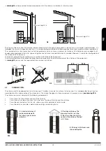
OUTSIDE AIR INTAKE
For the proper operation of the stove, it is essential that there is enough air for the combustion and re/oxygenation of the environment where
it is installed. This means that the air must be able to move for the combustion through some openings connected to the exterior, even when
doors and windows are closed.
It must be placed in so that it cannot be obstructed. It must be connected to the environment where the equipment is installed and it must be
protected by a grate. The minimum area of the outlet should not be less than 100 cm2.
When the air flow comes through openings that are connected to the exterior of adjacent environments, it is important to avoid air intakes in
connection with garages, kitchens, toilets, etc.
The stove is provided with a necessary air intake for the combustion on the back side (40 or 50 mm diameter). It is important this intake is not
blocked and to respect the recommended distances to the wall or near items.
It is recommended the primary air intake connection of the stove with the outside although it is not obligatory. The connection tube material
can be made in any material (PVC, aluminium, polyethylene, etc.), not necessarily metallic. Consider that inside this duct is going to pass air
at the outside temperature.
6
START UP
The ignition of this kind of equipments is automatic, so, please do not put on the burner any kind of material to ignition.
Before the ignition, follow the next verifications:
It is forbidden to use liquid substances such as alcohol, gasoline, petroleum or similar products. The use of this substance
leads the loss of warranty.
-
The electrical cable must be connected to the electrical network (230 Vac) with a socket equipped with earthing system.
-
The bipolar switch, placed on the rear side of the stove, must be in position I.
-
The pellet tank must be supplied.
-
The combustion chamber must be clean.
-
The burner must be clean and properly placed.
-
The combustion chamber door must be closed correctly.
During the first ignition could happen that the stove has finished the ignition cycle and there is no flame. In this case the stove automatically
starts an alarm state. This happens because the fuel feeder is empty and needs a moment to fill in. To solve this problem start again the stove
(taking into account the previous considerations ) until the flame appears.
The stove, at the beginning, must be subject to different start-up cycles so that all materials and the paint can complete different elastic
expansions.
At the beginning, it is possible that you note smoke or smell which are typically produced when metals are subject to high temperatures or
when the paint is still fresh. This paint is boiled at 80º C for a few minutes when construction, but it must exceed for a time the temperature of
200 ºC before the adhesion to the metallic surfaces.
Therefore, it is important to adopt these measures during the ignition phase:
1.
Assure that there is a good air refill in the place where the equipment is installed.
2.
During the firsts ignitions, keep a low power work and the oven lit during at least 6-10 hours continuously.
3.
Repeat this operation at least 4-5 times or more, depending on the needs.
4.
During the first ignitions, you should not place any object on the equipment and, in particular, on lacquered surfaces. Lacquered
surfaces should not be touched while the equipment is heated.
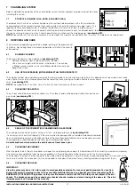
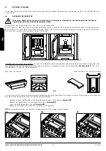
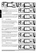
6.1
PLACING THE BAFFLE PLATE IN MODELS ALBA, KIRA AND NINA
Inside the fuel store (hopper) of models Alba and Kira you will find the stove baffle-plate. This piece must be placed on the top side of the
combustion chamber in order to the well work of the stove. Please, follow the next steps:
INSTALLATION, OPERATING AND SERVICING INSTRUCTIONS
AIR SERIES
EN
Summary of Contents for Air Series
Page 105: ...104 11 3 NINA FT ...
Page 121: ...120 11 11 SARA NC ...
Page 123: ...122 11 12 EVA FT ...
Page 125: ...124 11 13 EVA NC FT ...
Page 127: ...126 11 14 CORAL FT ...