Brocade Communications Systems DCX-4S Quick Start Manual Download Page 11

Brocade DCX-4S QuickStart Guide

11 of 20

Publication Number: 53-1001192-03

7. If applicable, lock the wheels of the lift.

8. Gently slide the chassis onto the final installation surface, ensuring that it remains supported during the 

transfer.

9. Ensure the chassis can be oriented so that the nonport side has access to intake air (cool).

10. Reinstall the vertical cable management fingers.

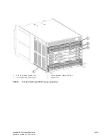
11. If ICL cables are not being used, ensure that EMI plugs are inserted in the ICL cable sockets in the core switch 

blades.

12. Reinstall the chassis door. The door must be installed to meet EMI compliance.

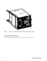
Providing power to the Brocade DCX-4S

DANGER

Use the supplied power cords. Ensure the facility power receptacle is the correct type, supplies the 
required voltage, and is properly grounded. (D004)

1. Connect the two AC power cords to each of the two power supplies.

2. Connect the power cords to a power source with a voltage of 200 to 240 VAC, 47 to 63 Hz.

3. Turn the AC power switches on the power supplies to ON. The AC power switches light green when switched on 

and power is supplied.

4. The Brocade DCX-4S performs a power-on self-test (POST) each time it is powered on. POST takes approximately 

ten minutes and is complete when the indicator light activity displays the operational state. 

You can bypass POST by using the fastBoot command. You can also disable POST for successive reboots on the 
Brocade DCX-4S using the diagDisablePost command.

ATTENTION

Do not connect the switch to the network until the IP addresses are configured.

Managing cables

ATTENTION

The minimum bend radius for a 50 micron cable is 2 in. under full tensile load and 1.2 in. with no tensile load. 

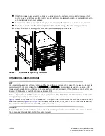
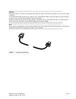
Cables can be organized and managed in a variety of ways: for example, using cable channels on the port or nonport 
sides of the cabinet or patch panels to minimize cable management. With the horizontal orientation of the blades in 
the DCX-4S, a pair of vertical cable management finger assemblies (

Figure 4

) have been provided to keep the cables 

from hanging down in front of other blades.

Following is a list of recommendations:

Leave at least 1 m (3.28 ft) of slack for each port cable. This provides room to remove and replace the 
Brocade DCX-4S, allows for inadvertent movement of the rack, and helps prevent the cables from being 
bent to less than the minimum bend radius.

Summary of Contents for DCX-4S

Page 1: ...53 1001192 03 53 1001192 03 53 1001192 03 23 November 2009 Brocade DCX 4S Backbone QuickStart Guide...

Page 2: ...ter programs that accompany it The product described by this document may contain open source software covered by the GNU General Public License or other open source license agreements To find out whi...

Page 3: ...4S Backbone as a standalone unit quickly Note the following additional documentation For detailed installation and configuration instructions refer to the Brocade DCX 4S Backbone Hardware Reference Ma...

Page 4: ...s A danger notice calls attention to a situation that is potentially lethal or extremely hazardous to people A lightning bolt symbol accompanies a danger notice to represent a dangerous electrical con...

Page 5: ...art Guide 5 of 20 Publication Number 53 1001192 03 FIGURE 1 Port side of the Brocade DCX 4S sample configuration 1 FC8 48 port blade example 4x 3 Control processor blade CP8 2x 2 Core switch blade CR4...

Page 6: ...ation Number 53 1001192 03 FIGURE 2 Port side of the Brocade DCX 4S with the port side exhaust kit installed sample configuration Brocade DCX 4S nonport side Figure 3 displays a sample configuration o...

Page 7: ...re Channel ports Configurations with fewer ports require less time These time estimates assume a prepared installation site and appropriate power and network connectivity 1 WWN card bezel logo plate 2...

Page 8: ...fault tolerance connect each power cord to a separate power source 3 Plan for cable management before installing the chassis Installing the rack mount kit or port side exhaust kit 30 minutes Refer to...

Page 9: ...brocade com products interop_and_compatibility jsp 5 Ensure that the air intake vents have a minimum of 2 inches of airspace 6 Ensure that the air temperature on the air intake side is less than 40 de...

Page 10: ...d install the Brocade DCX 4S a Cut the bands that encircle the packaging b Remove the lid and the kits and foam from the top of the chassis c Lift the cardboard box off the chassis and remove the plas...

Page 11: ...pplied 4 The Brocade DCX 4S performs a power on self test POST each time it is powered on POST takes approximately ten minutes and is complete when the indicator light activity displays the operationa...

Page 12: ...r removal of a license the license enforcement is performed on the ICL ports only when the portdisable and portenable commands are issued on the ports An ICL license must be installed on both Brocade...

Page 13: ...is to the right bottom connectors ICL 0 of the CR4S 8 blades in the second chassis Similarly connect the cables from the right bottom connectors ICL 0 of the CR4S 8 blades in the first chassis to the...

Page 14: ...n Number 53 1001192 03 FIGURE 6 ICL cable connections between two DCX 4S chassis 1 Chassis 1 5 ICL connector ICL 1 2 Core switch blades CR4S 8 6 ICL connector ICL 0 3 Control processor blades CP8 7 IC...

Page 15: ...core switch blades display a steady green light 2 Remove the shipping cap from the CONSOLE port on the active CP Use the serial cable provided with the Brocade DCX 4S to connect the CONSOLE port on th...

Page 16: ...in prompt CP0 Console Login 7 Log in to the Brocade DCX 4S as admin using the default password password You are prompted to change the default passwords at initial login swDir login admin Password Ple...

Page 17: ...ocade DCX 4S External IPs must not use these addresses 3 Set up the CP0 IP address by entering the ipaddrset cp 0 command swDir admin ipAddrSet cp 0 Enter the information at the prompts 4 Set up the C...

Page 18: ...eate an Ethernet connection to the Brocade DCX 4S follow these steps 1 Remove the shipping plug from the Ethernet port on the active CP blade 2 Insert one end of an Ethernet cable into the Ethernet po...

Page 19: ...6 port card installed and cables to the Fibre Channel ports The ports are color coded to indicate which can be used in the same port group for trunking trunking port groups can be up to 8 ports The p...

Page 20: ...trator s Guide for more information Backing up the configuration Save all key configuration data for the Brocade DCX 4S including license key information and upload it to a host for reference Routine...

Reviews: