background image

e-mail: 

[email protected]   

voice: 

360.854.9559   

fax: 

866.783.1742

25

WVRC-4 Installation and Operation Manual

WEB SETUP

WEBSITE:

Visit our web site for
product updates and
additional information.

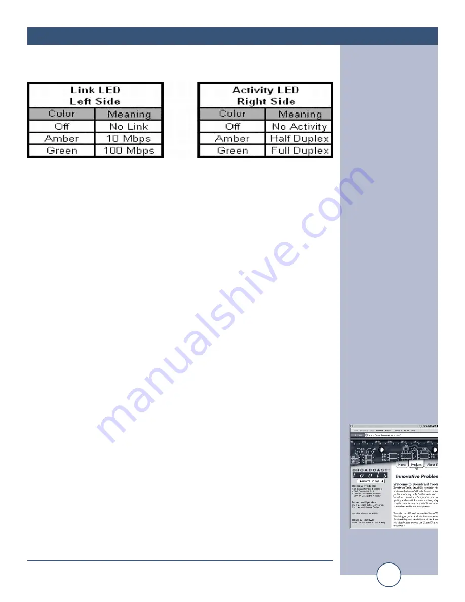
Ethernet port LED indicator functions

4 - Start the “Device Installer” software. 
a - Click on “SEARCH”
b - When the WVRC-4 is found, click on the listed device.  If more than one WVRC-4
is found, refer to the MAC address label attached to the WVRC-4 RJ-45 case and click
on the desired WVRC-4, which should be highlighted.  

NOTE:    The cover must be removed to locate the MAC address label, or check
the “MAC” label attached to the top of chassis.

c - Click on the “ASSIGN IP” button, then follow the instructions for setting a stat-
ic IP address, along with the subnet and gateway, if applicable.
d - After the WVRC-4 has rebooted, click the “SEARCH” button, the configured 
WVRC-4 should be listed.

NOTE:    You may have to click the search button more than once after the reboot.  

NOTE:    You can also open your browser and type in the assigned IP address
in the “ADDRESS” area of your browser.  Example:  192.168.1.101

5 - If you are behind a firewall or router, you will need to port forward not only port
80, also open ports 3001 and 3002 and set the SUN Java to direct.  

NOTE: To set up port forwarding, refer to the manual supplied with the fire-
wall or router.

6 - To change the WVRC-4 from port 80, contact the factory 

7 - To access the WVRC-4, open your browser and type in the assigned IP address
in the “ADDRESS” area of your browser.  Example:  192.168.1.55

8 - If things are working correctly, you should see the WVRC-4 web page. 

NOTE:  On some machines and browsers, this may take a few seconds.

9 - Log in using the default user name = wvrc4 or admin (lower case) and the 
password = wvrc4 (lower case) or 1234.  

NOTE:  If you change the “OWNER” user name and password, be sure to
write it down.

10 – Follow the descriptions on the following pages to set up the WVRC-4. 

Summary of Contents for WVRC-4

Page 1: ...k of Broadcast Tools Inc All Sentinel labeled products are a trademark of Broadcast Tools Inc Copyright 1989 2011 by Broadcast Tools Inc All rights reserved No part of this document may be reproduced or distributed without permission Visit www broadcasttools com for important product update information Network Agent Version 3 68 Manual Update 07 13 2011 PIC Firmware Version 1 12 or above CAUTION T...

Page 2: ...e Timer 14 Pager Numbers and Data Strings 15 Analog metering Setup 15 Status Setup 17 Recording Voice Prompts 18 Configure DIP Switch Settings 18 Dial up Operation 21 WEB and Dial Up Notice 22 Web Setup 23 Configuration Info 23 Ethernet Setup 25 Firmware 26 Java Applet 26 Main Screen 27 Login Dialog 28 User Setup Dialog 28 System Setup Dialog 29 Network Setup Dialog 30 Schedule Setup Dialog 31 Sch...

Page 3: ...rac tice is extremely dangerous and should never be attempted The pluggable euroblock screw terminals are not designed to shield humans from potentially dangerous volt ages Contact with high voltages can cause serious injury or death The maximum recommended voltage for the WVRC 4 is 30V Switching of high voltages should only be done external from the WVRC 4 and in a manner that isolates the voltag...

Page 4: ...fect to play when an out of tolerance alarm is generated We have also provided SNMP capabilities to allow multiple units to be monitored with any SMNP manager software package The WVRC 4 is equipped with four high resolution analog metering channels while each of the four optically isolated status channels may be configured for 5 to 24vdc wet or dry contact closures status monitoring The four cont...

Page 5: ... strikes and other high surges in voltage levels will damage your WVRC 4 and con nected equipment if it is not properly protected For lightning protection devices check out www polyphaser com and www itwlinx com UPS Standby Power System We recommend that you connect your WVRC 4 to a UPS system While all operat ing and user parameters are stored in non volatile EEPROM brownout conditions and lightn...

Page 6: ...d when the unit is off HOOK DV LED Illuminated when a valid DTMF tone is detected ALM LED Illuminated when unit is in an alarm condition PWR LED Illuminated when valid power is applied to the power jack PGM LED Illuminated when the unit is in programming mode SS LED Illuminated when adequate audio is applied to the SS input OFF when the level is to low and flashing if in an SS alarm condition if e...

Page 7: ...ult this terminal is ground When configured for WET floating this terminal is the Anode via a 2 2K ohm current limiting resistor BOTTOM 1B 4B Connector Status opto isolators This terminal is always the cathode BOTTOM R1NC R4NC Connector Normally closed dry relay contacts Raise function TOP R1CM R4CM Connector Common wiper dry relay contact Raise function TOP R1NO R4NO Connector Normally open dry r...

Page 8: ... that has a floating ground an isolation DC amplifier must be used Four analog metering channels are connected to the WVRC 4 via depluggable euro block screw terminals Connect the positive side of the source to the desired channel terminal labeled ANx where x is the channel number 1 through 4 and asso ciated GND ground terminal Each analog metering input can handle up to pos itive only 10 volts DC...

Page 9: ...controlled by the LOWER relays should be connected to the BOT TOM terminals labeled LxNC LxCM and LxNO where x is the channel number NOTE If mechanical latching relays are required we suggest the Broadcast Tools LR 5 4PDT 1SPST mechanical latching relay Power Failure Input Connect a user supplied 6 to 12 volts DC only power source center positive to the power failure input labeled PF The barrel co...

Page 10: ...rious service providers to get reliable control With some cellular phone services you may need to change the DTMF guard time jumper to the FAST position We recommend using a product from Telular Phonecell SX5D or SX7 which is designed for the GSM system www telular com PGM RJ11 TT phone Connect the modular cord of the user supplied TT telephone to the front panel RJ11 jack labeled PGM PGM RS 232 f...

Page 11: ...mpts NOTE The dial up programming may be accomplished locally using the RS 232 serial port or via the web using Telnet Telnet DIAL UP programming via LAN WAN NOTE Step by step HyperTerminal Telnet setup instructions are available on line at www broadcasttools com under Downloads If you have followed the above HyperTerminal Telnet steps the main WVRC 4 menu will be displayed on the next page Local ...

Page 12: ...previous menu selection and if pressed from the PGM Menu program mode will be exited Dial Out Numbers These are the numbers that will be dialed when alarms are generated The dial out list will select numbers from this pool to call out during an alarm condition Up to 32 digits can be used in each number along with a comma for one second and a semi colon for 5 second pauses When 1 is selected from t...

Page 13: ...aled for a selected input alarm 1 4 is used for status inputs A D are used for Analog metering inputs S for Silence Sensor P for Power Fail and T for Temperature The numbers after the Analog letter selection show which analog channel is being selected Only enter the letter designation to select the analog dial out list to program Example When status input 1 changes state the WVRC 4 will dial the n...

Page 14: ...n 7 3 min 8 4 0 min and 9 5 0 min Note The silence sensor audio must be restored for a minimum of 10 seconds and the alarm must be acknowledged before it is cleared Power Fail Time is programmed in 10 second values For example 2 20 seconds of silence or power failure to generate an alarm 9 90 seconds If it is set to 0 the alarm will be turned off and will not call out The HU value refers to the nu...

Page 15: ...r a temperature alarm 20 for a power failure 21 24 for sta tus inputs one through four and 29 for a silence sensor alarm The last item to be sent is the pager data This can be used to identify the station or location of the WVRC 4 The comma can be used any place in the dialing strings to place a one second pause and the semi colon for a five second pause Analog metering Setup When 5 is selected fr...

Page 16: ...MUST be present for several seconds prior to entering OP PGM mode Once program mode is entered the analog metering inputs are locked and changes made while in program mode will not be read If there is no signal on the input an error mes sage will be displayed Enter a 2 from the Analog Set Up menu to establish alarm set points Analog metering input set points are set up using items 1 à 4 representi...

Page 17: ...e first digit is a 1 then Celsius is assumed Example To enter low and high alarm set points of 30F and 95F enter 0030 0095 To enter low and high alarm set points of 10C and 40C enter 1010 1040 Do not enter the it will be entered automatically Status Setup When 6 is selected from the PGM Menu the Status inputs are set up for either Normally Open or Normally Closed and for the amount of DEBounce tim...

Page 18: ... 2 Press the front panel OP PGM button this should illuminate the front panel PGM LED 3 Enter the two digit address of the message you wish to program The list of messages are below 4 The Red REC LED will illuminate As soon as it lights begin speaking the new message into the telephones mouth piece For best results stay at least three inches from the mouthpiece of the telephone 5 When finished pre...

Page 19: ... Status Input 4 14 5 Status Input 5 15 5 Status Input 6 16 5 Status Input 7 17 5 Status Input 8 18 5 Analog Input 1 21 5 Analog Input 2 22 5 Analog Input 3 23 5 Analog Input 4 24 5 Analog Input 5 25 5 Analog Input 6 26 5 Analog Input 7 27 5 Analog input 8 28 5 Engineering Unit 1 31 2 6 Engineering Unit 2 32 2 6 Engineering Unit 3 33 2 6 Engineering Unit 4 34 2 6 Engineering Unit 5 35 2 6 Engineeri...

Page 20: ... 6 Temperature Alarm 67 2 6 CONFIGURE DIP Switch settings NOTE The UP position is OFF DIP 1 Feature creep DIP 2 OFF Voice Temperature in Fahrenheit ON Celsius DIP 3 If OFF description messages will be played when controlled via dial up If ON raise and lower description messages will not be played DIP 4 OFF Server control ON PC control via DB9 DIP 5 OFF Normal operation ON DB9 RS 232 to web server ...

Page 21: ...ter 1 analog value 1 will play The number 1 Lower relay will be held on as long as received Raise relay held on as long as received If DIP3 is OFF the associated relay message plus raise or lower will be played after the or is released To find out the new analog values just press 1 again and it will speak the new value Audio I O functions are controlled with the following codes once the security c...

Page 22: ... Enable Status 4 alarm 7741 Disable Status 4 alarm 7740 Poll Status 4 alarm enable 7749 Enable Analog 1 alarm 7811 Disable Analog 5 alarm 7810 Poll Analog 1 alarm enable 7819 Enable Power Fail Alarm 7911 Disable Power Fail alarm 7910 Poll Power Fail alarm enable 7919 Enable Silent Sensor Alarm 7921 Disable Silent Sensor Alarm 7920 Poll Silent Sensor Alarm enable 7929 NOTE To clear an alarm press t...

Page 23: ...ic IP isn t available consider using http www dynip com 2 The network s subnet mask 3 Your network s gateway address essential for proper operation 4 The IP address of the email server 5 The SMTP port used by your email server usually 25 6 Up to four email addresses to which you want to send alarms NOTE The network administrator may be required to enter the IP address of the WVRC 4 into the SMTP s...

Page 24: ...all the Device Installer software on the PC used for the WVRC 4 setup NOTE The WVRC 4 applet requires a compatible Java Runtime Environment Version 6 update 1 or greater If your browser is lacking Version 6 update 1 or greater we have provided a link to download the required appli cation http www java com en download index jsp then click on the Download Now button then follow the prompts 2 Connect...

Page 25: ... 4 should be listed NOTE You may have to click the search button more than once after the reboot NOTE You can also open your browser and type in the assigned IP address in the ADDRESS area of your browser Example 192 168 1 101 5 If you are behind a firewall or router you will need to port forward not only port 80 also open ports 3001 and 3002 and set the SUN Java to direct NOTE To set up port forw...

Page 26: ...ware communicates with the WVRC 4 microcontroller via its internal seri al port and provides several network interfaces via its Ethernet port The WVRC 4 firmware supports an HTTP web interface on TCP port 80 The default page index html contains a Java applet used to monitor and control the WVRC 4 The applet is fully described in the next section CAUTION NEVER DOWNLOAD FIRMWARE UPDATES OR CHANGES T...

Page 27: ...aphical representation of the defined analog metering values Analog Text Numeric representation of the defined analog values Analog Unit Labels User defined labels giving analog units of measure Status Labels User defined labels for status inputs Status LED s On Off indicators showing current state of status inputs Relay Button Labels User defined labels for relays Relay Buttons Buttons to momenta...

Page 28: ...cribed below Silence Alarms Sends the Silence clear Alarms command to the WVRC 4 Show Log Displays the event log as a text file in the browser IP log txt Be sure to allow pop ups User Defined Button Displays a user defined label and activates a user defined URL when clicked Example URL of site camera etc About Displays the About dialog described below Login Dialog The Login dialog asks the user fo...

Page 29: ...s and exits Cancel Exits without saving settings Default Username wvrc4 or admin lower case Default Password wvrc4 lower case or 1234 System Setup Dialog The Unit Setup dialog allows the user to set up the following operating characteris tics of the WVRC 4 firmware and applet Site ID Changes the site ID displayed on the main page Station Call Letters Changes the station call letters displayed on t...

Page 30: ... four of alert recipients Backup DNS Server IP address of DNS server to use when DHCP is not used to acquire an IP address for the WVRC 4 or if the DNS server address is not provided in the DHCP response NTP Server Address Time server address NTP Port Time server port usually 123 NTP update Interval Specifies how frequently the WVRC 4 acquires time More frequent updates ensure more precise time NT...

Page 31: ...e time or repeating events The Schedule Setup Dialog displays a list of scheduled events and allows the user to edit the schedule event s details described under Schedule Detail Dialog below Edit Opens the Schedule Detail Dialog for the selected event The user can also double click the event to open the detail dialog Delete Delete the selected event Close Close the Schedule Setup Dialog Schedule D...

Page 32: ...vent should occur every calendar day Day of Week Check the day s of the week on which the event should occur Check all boxes if the event should occur every day of the week Hour Select the hour when the event should occur or ALL if the event should occur every hour Minute Select the minute when the event should occur or ALL if the event should occur every minute Second Select the second when the e...

Page 33: ...nalog value exceeds this value Alert Flag Enables alerts for this analog register Email Recipients Specifies which e mail recipients receive the alert Set Sets parameters for the analog channel using the current actual value Close Exit the analog setup dialog NOTE The analog value portion of the display will flash for any channel in an alarm condition and will cause the PC to beep if enabled Statu...

Page 34: ...p to four virtual channels These are similar to ana log channels but their values are derived from the product of two real analog chan nels and a constant Label Changes the label associated with any of the virtual channels Units Changes the engineering units label of any virtual channel Analog 1 Selects the first of two analog channels used in the calculation Analog 2 Selects the second of two ana...

Page 35: ...83 1742 35 WVRC 4 Installation and Operation Manual WEB SETUP About Dialog The About dialog displays the firmware version number Broadcast Tools contact information web link and e mail link WEBSITE Visit our web site for product updates and additional information ...

Page 36: ...r internal 5 VDC source Dry Open collector contact closures to ground or external source Power Failure opto isolated input 6 to 12vDC 50ma 2 1mm x 5 5mm coaxial connector Connectors Analog metering Status Relays and Audio I O Plug in euroblock screw terminals Telco Standard POTS line Protocols TCP IP UDP IP ARP ICMP SNMP TFTP Telnet DHCP BOOTP HTTP and AutoIP EMI FCC Compliance See the Declaration...

Page 37: ...OTHER WARRANTIES OR REMEDIES TO THE MAXIMUM EXTENT PERMITTED BYAPPLICABLE LAW BROADCAST TOOLSAND ITS SUPPLIERS DISCLAIMALL OTHER WARRANTIES EITHER EXPRESS OR IMPLIED INCLUDING BUT NOT LIMITED TO IMPLIED WARRANTIES OF MERCHANTABIL ITY OR FITNESS FOR A PARTICULAR PURPOSE AND THE FOREGOING ALTERNATIVE REMEDIES SHALL BE EXCLUSIVE OF ALL OTHER REMEDIES THIS LIMITED WARRANTY GIVES YOU SPECIFIC LEGAL RIG...

Page 38: ...022 1998 IEC CSPIR22 1993 Radiated RF emissions 30MHz 1000MHz Conducted RF Emissions Telecom Lines 150KHz 30MHz FCC Part 15 Subpart B Class B IEC 1000 3 2 A14 2000 IEC 1000 3 3 1994 Electromagnetic Immunity EN55024 1998 Information Technology Equipment Immunity Characteristics Direct ESD Contact Discharge Indirect ESD Radiated RF Electromagnetic Field Test Electrical Fast Transient Burst Immunity ...

Page 39: ...asttools com Copyright 1989 2011 by Broadcast Tools Inc All Rights Reserved Broadcast Tools Connection suggestion when using listed equipment with DSL Telco Phone Lines Modification Date 07 12 11 DSL MODEM Ethernet RJ11 Duplex Adapter DSL Filter Required for proper operation DC 8A DC 8 Plus Site Sentinel 8 w Voice STA III STI II VAD 2 VAD 2 Plus WVRC 4 WVRC 8 RJ11 Modular Cable RJ11 Modular Cable ...

Reviews: