background image

e-mail: 

[email protected]   

voice: 

360.854.9559   

fax: 

866-783-1742 

8

VAD-2 Installation and Operation Manual

INSTALLATION

INSTALLATION

Installation of the VAD-2 in high RF environments should be performed with care.
Shielded cable is suggested for all control and the audio output.   All shields should
be tied to the 

“CGND”

terminals.   The station ground should be connected to the

chassis ground screw located on the far right side of the VAD-2 as viewed from the
rear.   It is recommended that all cables connected to the VAD-2 be looped through
ferrite cores to suppress RF.   Surge protection with RF filtering such as the Tripp
Lite “ISOBAR 4 or 6” is also suggested for the wall transformer.   The purchase of
an inexpensive UPS will provide back-up power in case of a power outage.

Connecting your equipment

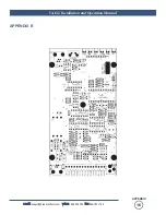
The VAD-2 interfaces to your equipment through the rear panel screw terminals.
Follow the legends for the desired relays, inputs and audio output connections,
which appear on the lip of the printed circuit board and also on the layout drawing
on the last page of this manual.   Strip each conductor and insert the conductor into
the terminal and screw down the capture screw.   The terminals accommodate wire
sizes from 18 - 28 AWG solid or stranded wire.

Status Inputs

Connection for input 1 is made between the terminal labeled “IN-1” and Ground, while
input 2 may be connected to the terminal labeled “IN-2” and the ground terminal.

Silence Sensor inputs

These are stereo 10 k ohm unbalanced inputs and are summed together and moni-
tored for silence.   

BOTH

channels 

MUST

go silent to trip an alarm.   The alarm

threshold is set at –20dbu.   Connect your unbalanced source equipment to either or
both inputs and tie the ground to the 

“AGND”

terminal.   If your source equipment

is balanced, use the "+" and GND terminal from the source.   

Do not connect the "-"

terminal to ground of your source equipment. 

Shields should be tied to the

“CGND”

terminals.   The SS LED is illuminated when you have audio applied to

the inputs.   When the SS is in an alarm condition, the SS LED will flash.   The time
delay is user programmable for 10, 30, 60 (seconds) 1.5, 2, 2.5, 3, 4, & 5 minutes.
Factory default is (0) OFF.

Relays

Connection for relay one is between the K1-A and K1-B terminals.   Relay two is
between terminals K2-A and K2-B.   Limit contact current to 1 amp at 30 vdc.

Note:  For safety, never connect 120 Vac circuits to these relays!

Telephone “CALLER” line level output

Balanced CALLER telephone line audio output is available between the Aud-A and
Aud-B terminals.

NOTE:

NOTE:  Some features
may require the remov-
ing of the chassis cover.
Caution should be
observed.  Hazardous
voltages may be present
on the printed circuit
board.

NOTE:

Both status inputs
employ a 4 second
debounce (response
delay).

NOTE:

The 5-vdc TTL/CMOS
compatible inputs are
configured as a divider.
A low input must be
between 0 and + .6 vdc,
while a high must be
b 4.00 and +
5.00 vdc.  This should
help in noisy (RF, etc)
environments.  

Summary of Contents for Tiny Tools VAD-2

Page 1: ...formation or new editions may be issued to incorporate such changes Broadcast Tools is a registered trademark of Broadcast Tools Inc Copyright 1989 2011 by Broadcast Tools Inc All rights reserved No part of this document may be reproduced or distributed without permission Visit www broadcasttools com for important product update information Firmware version 1 09 and above Manual update 07 13 2011 ...

Page 2: ... Title Page Introduction 3 Safety Information 3 Who to Contact for Help 3 Product Description 4 Applications 4 Inspection 5 Programming 5 Installation 8 Operation 10 Specifications 13 Warranty 14 Component Layout Appendix Connection Suggestion Appendix WEBSITE Visit our web site for product updates and additional information 2 CONTENTS ...

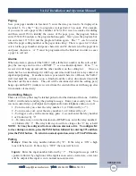
Page 3: ...blems If you experience these problems please research your hardware software instruction man uals or contact the manufacturers technical support department WHO TO CONTACT FOR HELP If you have any questions regarding your product or you need assistance please con tact your distributor from whom you purchased this equipment If you would like more information about Broadcast Tools products you may r...

Page 4: ... is the ability to be programmed for normal operation or configured to close when an alarm is activated Features Two user programmable normally open or closed status inputs Stereo Silence Sensor with programmable alarm time delay Two SPST one amp relays with momentary latching or tone duration operation Local and remote programming and recording Remote security and program access codes Stores up t...

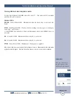
Page 5: ...ot Press in the front panel recessed PGM button When the program button is pressed the RED PGM led will flash to confirm that it has been placed in program mode Enter 118540808 and then press the PGM button again The VAD 2 may also be remotely programmed using the access code All features can be programmed remotely with the exception of the access code itself so that it can not be inadvertently ch...

Page 6: ... Code 22nnnnnnnn Default 456 Example 22456 Lap Ring Repeat 1 Repeat 2 Repeat 3 Silence Sensor delay timer 23LRPPPS program all six at once single digits 1 8 except the silence sensor timer 0 to 9 Example 23324441 This example would set the number of laps to 3 the VAD 2 would pick up in 2 rings repeat 4 times for inputs 1 thru 3 and a silence sensor delay of 10 seconds Note Silence sensor time dela...

Page 7: ...hen the Silence Sensor alarms the VAD 2 will dial the number stored in location 11 then the numbers in 12 13 and 14 Input 1 Description 51 Record Input 1 Message 3 Seconds Example 51 Satellite Receiver failure Input 2 Description 52 Record Input 2 Message 3 Seconds Example 52 Power Failure Input 3 Silence Sensor Description 53 Record Input 3 Message 3 Seconds Example 53 Silence Monitor failure Gre...

Page 8: ...cted to the terminal labeled IN 2 and the ground terminal Silence Sensor inputs These are stereo 10 k ohm unbalanced inputs and are summed together and moni tored for silence BOTH channels MUST go silent to trip an alarm The alarm threshold is set at 20dbu Connect your unbalanced source equipment to either or both inputs and tie the ground to the AGND terminal If your source equipment is balanced ...

Page 9: ...entral office Loop Start ONLY POTS line here This line MUST be equipped with CPC Calling Party Control WINK or COD to properly function Guard Time Setting This feature allows you to set how fast the DTMF tones are detected Factory default is set at Medium The four position timing header JP 3 selections Fast 50 ms Medium 100 ms Slow 150 ms Mounting The VAD 2 may be set on a desktop mounted on a wal...

Page 10: ...mmed into the repeat memory If there is no acknowledgment the VAD 2 will go on to the next number and so on until all numbers stored in that Input s dial list have been called This process will then be repeated for the number of times stored in the lap memory The lap memory is global and is the same for both inputs while the repeat memory is programmable by input After reporting the VAD 2 is ready...

Page 11: ...ent session is finished and the call is disconnected and will then dial out the new alarm The call will be disconnected after the calling party hangs up and the CPC wink is received from the central office or will hang up after two minutes of inactivity Controlling Relays There are two relays that may be latched pulsed or for the duration of the tone Call the VAD 2 it will answer and play the gree...

Page 12: ...am LED Flashes when recording voice messages or configura tion setup Also used as a valid DTMF tone indicator which will illuminate when valid DTMF tones are decoded K1 Green K1 LED Illuminated when relay K1 is activated K2 Green K2 LED Illuminated when relay K2 is activated PWR Green Power LED Illuminated when power is applied SS Green Red on some models Stereo Silence Sensor Illuminated with val...

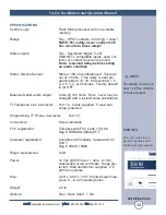
Page 13: ...s Factory default is 0 OFF Balanced caller audio output 0 dbu 100 ohms Note Level may be changed with a resistor value substitution TT Telephone Line Connector RJ 11C Cable supplied Fused and surge protected Programming TT Phone Connector RJ 11C Connectors Screw terminals FCC registration Complies with FCC parts 15 68 Reg BRDUSA 36042 OT T Canadian registration Complies with Industry Canada CS 03 ...

Page 14: ...THER WARRANTIES OR REMEDIES TO THE MAXIMUM EXTENT PERMITTED BYAPPLICABLE LAW BROADCAST TOOLSAND ITS SUPPLIERS DISCLAIMALL OTHER WARRANTIES EITHER EXPRESS OR IMPLIED INCLUDING BUT NOT LIMITED TO IMPLIED WARRANTIES OF MERCHANTABIL ITY OR FITNESS FOR A PARTICULAR PURPOSE AND THE FOREGOING ALTERNATIVE REMEDIES SHALL BE EXCLUSIVE OF ALL OTHER REMEDIES THIS LIMITED WARRANTY GIVES YOU SPECIFIC LEGAL RIGH...

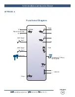
Page 15: ...866 783 1742 15 VAD 2 Installation and Operation Manual APPENDIX APPENDIX A Functional Diagram LT Silence Sensor Input Relays RT Alarm Trigger Input 1 Alarm Trigger Input 2 Telco Line Programming TT Phone user supplied Power SS Alarm K1 K2 Hook PGM Caller Out ...

Page 16: ...e mail support broadcasttools com voice 360 854 9559 fax 866 783 1742 16 VAD 2 Installation and Operation Manual APPENDIX APPENDIX B ...

Page 17: ...e mail support broadcasttools com voice 360 854 9559 fax 866 783 1742 VAD 2 Installation and Operation Manual 17 APPENDIX ...

Reviews: