background image

This system applies to 4 wheeled vehicles with meridian tyre (vacuum tyre) and cold tyre pressure (22ºC) lower than 2.8 bar

(280KPa/40.6psi/2.86*10

4

kgf/m

2

). It should be installed by a qualified professional according to this manual.  This system is an

electronic device that measures and displays the inside air pressure and temperature of the tyres and gives a warning signal when

an abnormality is detected. The system has no controlling function so the driver should rectify and detected problems as soon as

possible. The performance of the sensors could be affected by chemical materials. Preset pressure from the manufacturer is 2.40

Bar (240KPa/34.8psi/2.45*10

4

kgf/m

2

). Please set it to your vehicles recommended pressures after the initial installation (see

details on page 14). This system is to be used as a monitoring aid only and Britpart will take no responsibility after the kit is installed

and the user must ensure tyres are inflated to the vehicle manufacturers recommendations.

Notification

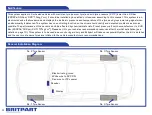
General Installation Diagram

No. 2 Tyre Sensor

No. 3 Tyre Sensor

No. 1 Tyre Sensor

No. 4 Tyre Sensor

Display

Receiver

Black wire to ground

White wire to ACC ON

Red wire to +12v power

4

Summary of Contents for DA4512

Page 1: ......

Page 2: ...2 ...

Page 3: ...edy the problem Keeping your tyres in good condition at the right pressure can extend the life of your tyres and reduce fuel consumption Please read this manual carefully before using our product Index Notification 4 General Installation Diagram 4 Working Principle 5 Components 5 Technical Specifications 6 Installation Sensor Installation 7 Display and Receiver Installation 8 Operation System Oper...

Page 4: ...oblems as soon as possible The performance of the sensors could be affected by chemical materials Preset pressure from the manufacturer is 2 40 Bar 240KPa 34 8psi 2 45 104kgf m2 Please set it to your vehicles recommended pressures after the initial installation see details on page 14 This system is to be used as a monitoring aid only and Britpart will take no responsibility after the kit is instal...

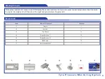
Page 5: ...its the signal the display unit will then show the signal and give an alarm if appropriate Working Principle Components Tyre Pressure Monitoring System 5 1 2 3 4 5 6 7 Code Name of Component Quantity 1 Display 1 2 Receiver 1 3 Tyre Sensor 4 4 Display Bracket 1 2 5 Display Bracket 2 1 6 3M Sticker 2 7 Instruction Manual 1 ...

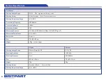
Page 6: ... Modulating Method FSK Measurable Pressure 0 3 5bar 0 350KPa 0 50 8psi 0 3 58 104kgf m2 Measurable Temperature 40 120ºC Battery Life 5 years Size 76 x 56 x 22mm Weight 38g no valve weight Display Receiver Working Voltage Range Receiver Supply 5v DC 9 15v DC Receiving Sensitivity N A 100dBm Receiving Frequency N A 433 92MHz Size 83 x 41 x 18mm 75 x 55 x 17mm Weight 70g 35g Working Current Standby 3...

Page 7: ...is front left wheel No 2 is front right wheel No 3 is rear right wheel and No 4 is rear left wheel Install the tyre and charge it with air to normal pressure then turn it to balance it Install the wheel Installation Remove the original air valve Tyre Pressure Monitoring System 7 Fix the sensor Charge the tyre to standard pressure then balance the wheel Tighten the screw in the sensor according to ...

Page 8: ...eceiving antenna Display bracket 1 Display bracket 2 ACC ON Recommended Install the display in front of the dashboard Recommended Install the display in an easy to see place Connect the red wire to 12 power supply white wire to the ACC ON black wire to ground Display and Receiver Installation Fix the display on a suitable position with the bracket or 3M sticker 3M sticker ...

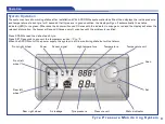
Page 9: ...d 3 times with the indicator in orange or red and the display will show the relevant information the buzzer will sound 3 times every 3 minutes until the problem is rectified Press SCAN to read the data of each tyre Press SET 3 seconds to convert the temperature units ºC to ºF When the ACC ON cut off the power supply the system is still in monitoring state but will not alarm Front right wheel Power...

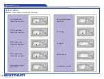
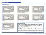
Page 10: ...ion continued 10 15 lower than reference pressure 20 lower than reference pressure 20 higher than reference pressure 25 higher than reference pressure Temperature higher than 70ºC Temperature higher than 80ºC Air leaking No signal Faulty sensor Low battery sensor ...

Page 11: ...w ID d Learn ID by LF Enter into setup mode Switch to ACC ON press SET until you hear the sound of Bi to enter setup mode Press SCAN to choose amongst the interfaces of a to g press SET again to enter into the setup mode Quit setup mode Press SCAN and select the interface g Then press SET to quit setup mode The system will quit setup mode automatically when the power supply is shut off ...

Page 12: ...the Temperature Unit Setting the present temperature unit will be displayed c Press SCAN you can shift between ºC and ºF d Press SET to confirm the temperature unit The system will quit setup mode of temperature unit in case of no operation in 10 seconds the original setting will be kept unchanged The system will enter into next setup interface automatically after setting or automatic quitting ...

Page 13: ...er the Pressure Unit Setting the present pressure unit will be displayed c Press SCAN you can shift between Bar and PSI d Press SET to confirm the setting of new pressure unit The system will quit the pressure unit setting mode in case of no operation in 10 seconds the original pressure unit setting will not be changed The system will enter into next setup interface automatically after setting or ...

Page 14: ...essure c Press SCAN the pressure will increase by 0 1bar or 1psi and will cycle among 0 5 2 8bar or 7 41psi d Press SET after confirming the new reference pressure e The system will enter into the reference pressure setting of back tyres automatically after setting front tyres pressure and show the current reference pressure Set the new reference pressure step c and d f The system will quit refere...

Page 15: ...hange b Press SET to enter the ID Exchange mode It will show the position of the front left wheel and its ID c Press SCAN select the front right wheel then press SET to confirm d Press SCAN select the back right wheel indicator of selected tyre will be kept unchanged e Press SET to finish the ID Exchange The system will quit ID exchange mode automatically in case of no operation in 10 seconds the ...

Page 16: ...sensor into the range of 10cm from the display Repeat the steps to learn other ID f The original ID will be replaced when the system receives a new one the setting is finished The system will quit Learn New ID mode automatically in case of no operation in 1 minute the ID will not be exchanged The system will enter into next setup interface after setting or automatic quitting Learn New ID When a se...

Page 17: ... or updated and then send out the data d The original ID will be replaced when the system received all the new data the setting is finished Press SCAN to quit the setting mode and keep the original setting unchanged The system will enter into next setup interface after setting or automatic quitting b Press SET to enter the LF Learn ID mode the system will indicate the position of all the wheels wa...

Page 18: ...72 1 0 986923 10 1972 103 750 061 14 5038 atm 1 01325 105 10332 3 1 03323 1 01325 1 10 3323 103 760 14 6959 mmH2O 0 101972 1 105 8 1 10 4 9 80665 10 5 9 67841 10 5 1 73 5559 10 3 1 42233 10 3 mmHg 133 322 13 5951 0 00135951 0 00133322 0 00131579 13 5951 1 0 0193368 lb in2 psi 6 89476 103 703 072 0 0703072 0 0689476 0 0680462 703 072 51 7151 1 Conversion table of temperature units ºF ºC 9 5 32 ºC º...

Page 19: ...Tyre Pressure Monitoring System 19 ...

Page 20: ......

Reviews: