background image


LD-POWER240 

BRITEQ


  10A 

5. Menu 

Press the button to select the programming functions. 

6. Up 

Press the button to go forward for the desired functions. 

7. Enter 

Press the button to confirm the selected functions. 

8. Down


Press the button to go backward for the desired functions. 

9. Display 

To show the various menu and selected function 


10.Chase Group 1 

Press the button to run chase group 1, the LED will be on. 

11.Chase Group 2 

Press the button to run chase group 2, the LED will be on. 

12.Chase Group 3 

Press the button to run chase group 3, the LED will be on. 

13.Manual 

Press the button into manual mode, the LED will be on. 

14.Fade 

Press the button into fade mode, the LED will be on. 

15.Auto 

Press the button into auto mode, the LED will be on. 

16.Blackout 

Press the button to blackout the unit, the LED will be on. 


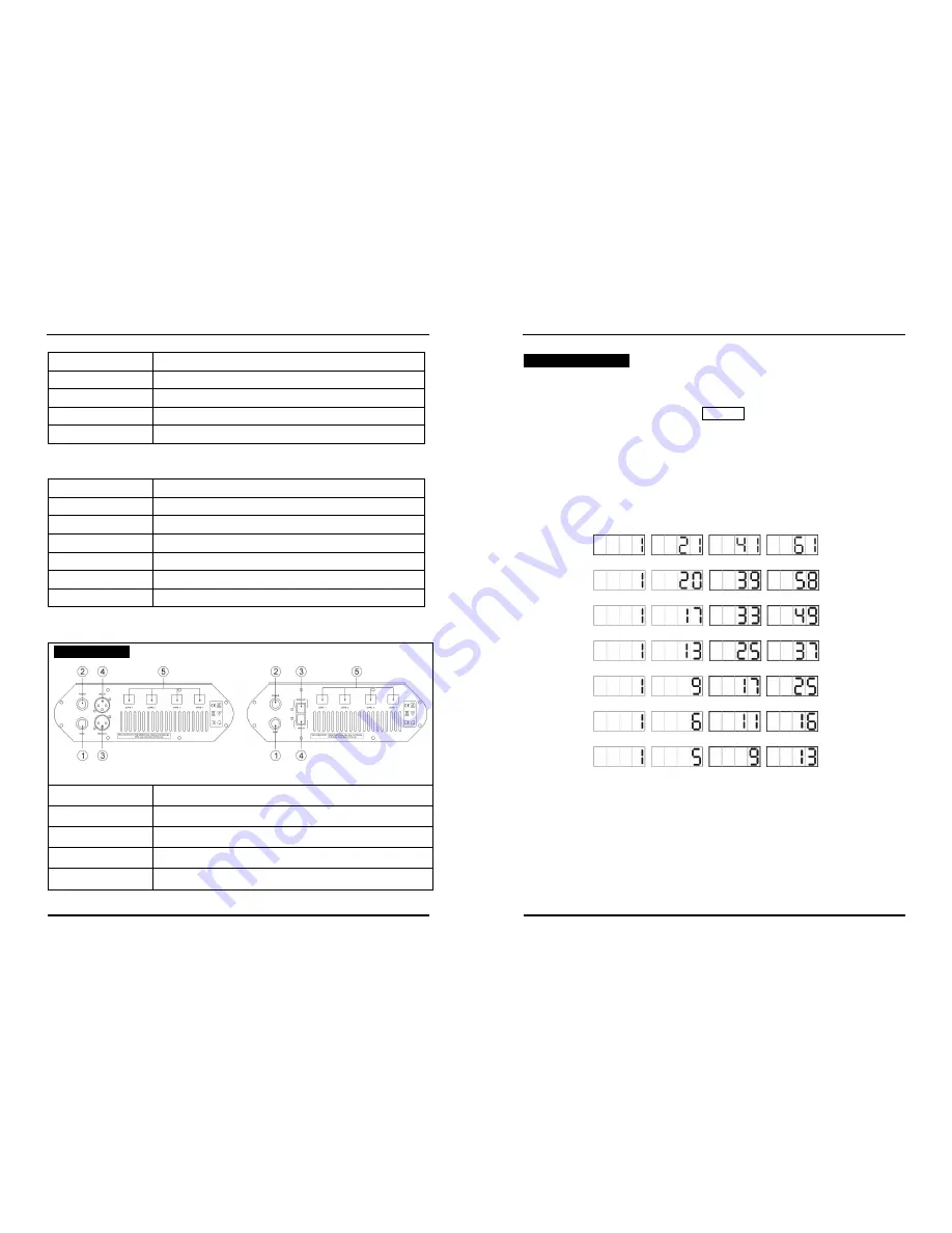
  6.2 Rear View   


1. FUSE


For protecting the unit when the transient current is too big. 

2. POWER 


Power cable for AC input.   

3. DMX OUT 

DMX Output 3 pin XLR socket 

4. DMX IN 

DMX Input 3 pin XLR socket 

5. LED 

DC power & signal output for linking LED fixtures. 


LD-POWER240 

BRITEQ


  11A 

7. DMX Controller   

Using universal  DMX  controller  to  control  the  units,  you  have  to  set  DMX  address 

from 1 to 512 channel so that the units can receive DMX signal. 

Press the 

MENU

 button up to when the 

Address

 is showing on the display. Pressing 

ENTER

 button and the display will blink. Use 

DOWN

 and 

UP

 button to change the 

DMX512  address.  Once  the  address  has  been  selected,  press 

ENTER

  button  to 

setup  (or  automatically return to the main functions without any change after  idling 

one minute). Back to the previous function without any change, press 

MENU

 button. 

Please refer to the following diagram to address your DMX512 channel for the first 4 

units.   

20 Channels:   


19 Channels:   


16 Channels:   


12 Channels:   


8 Channels:     


5 Channels:


4 Channels:     


Summary of Contents for LD-POWER240

Page 1: ...POWER240 BRITEQ 1A TABLE OF CONTENTS 1 Safety Instruction 2 Features 3 Technical Specification 4 Installing Instructions 5 Main Function 6 Overview 6 1 Front View 6 2 Rear View 7 DMX Controller 8 DMX...

Page 2: ...the unit 2 Features 7 Channel modes Mode 1 Mode 2 for RGBW Mode 3 Mode 4 for RGB Mode 5 Mode 6 for CW and WW colors Mode 7 for single color enables V Power to control passive lighting fixtures that f...

Page 3: ...e functions without any change press MENU button Press MENU button for 3 seconds to exit the functions press Chase Group 1 Chase Group 2 or Chase Group 3 button to run the built in chase or you have p...

Page 4: ...TER button to setup Back to the previous function without any change please press the MENU button Adjust Time Press the MENU button up to when the Adjust Time is showing on the display Press ENTER but...

Page 5: ...showing on the display Press ENTER button and 1 will blink use DOWN UP button to choose P output all or 1 4 10 press ENTER button to store use DOWN UP to set R Red G Green B Blue press ENTER button t...

Page 6: ...on 6 2 Rear View 1 FUSE For protecting the unit when the transient current is too big 2 POWER Power cable for AC input 3 DMX OUT DMX Output 3 pin XLR socket 4 DMX IN DMX Input 3 pin XLR socket 5 LED...

Page 7: ...LD POWER240 BRITEQ 12A 8 DMX512 Configuration 19 Channels 16 Channels 12 Channels LD POWER240 BRITEQ 13A 4 Channels 8 Channels 5 Channels 4 Channels...

Page 8: ...asily distort the signal and shut down the system 4 The DMX output and input connectors are pass through to maintain the DMX circuit when one of the units power is disconnected 5 Each unit needs to ha...

Reviews: