BriteMED MMS-21C User Manual Download Page 54


MMS-21C User Manual 

Page 54 


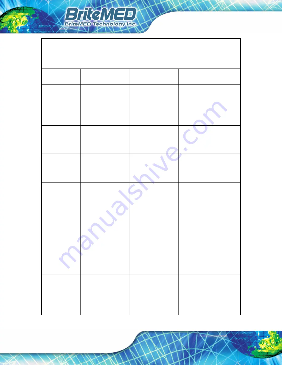
Guidance and manufacturer’s declaration – electromagnetic immunity


This LCD monitor is intended for use in the electromagnetic environment specified below. 
The customer or the user of the LCD monitor should assure that it is used in such an environment. 

Immunity test 

IEC 60601 test level  Compliance level 

Electromagnetic 

environment – guidance 

Electrostatic 
discharge (ESD) 
IEC 61000-4-2 

Contact: ±8 kV   
Air: ±15 kV 

Contact: ±8 kV   
Air: ±15 kV 

Floors should be wood, 
concrete or ceramic tile. If 
floors are covered with 
synthetic material, the 
relative humidity should be 
at least 30%. 

Electrical fast 
transient/burst 
IEC 61000-4-4 

5/50ns, 100kHz,   
±2kV 

5/50ns, 100kHz,   
±2kV 

Mains power quality should 
be similar to that of a typical 
commercial or hospital 
environment. 

Surge 
IEC 61000-4-5 

1.2/50 (8/20) µs   
LtL: ±1.0 kV     
LtG: ±2.0 kV 

1.2/50 (8/20) µs   
LtL: ±1.0 kV     
LtG: ±2.0 kV 

Mains power quality should 
be similar to that of a typical 
commercial or hospital 
environment. 

Voltage dips, 
short Interruptions 
and voltage 
variations on 
power supply 
input lines   
IEC 61000-4-11 

0 % 

U

T for 0.5 cycle 

(1 phase)   
0% 

U

T for 1 cycle 

70% 

U

T for 25/30 

cycles (50/60 Hz)   
0% 

U

T for 250/300 

cycles (50/60 Hz) 

0 % 

U

T for 0.5 cycle 

(1 phase)   
0% 

U

T for 1 cycle 

70% 

U

T for 25/30 

cycles (50/60 Hz)   
0% 

U

T for 250/300 

cycles (50/60 Hz) 

Main power quality should be 
that of a typical commercial or 
hospital environment. If the 
user of monitor requires 
continued operation during 
power mains interruptions, it 
is recommended that monitor 
be powered from an 
uninterruptible power supply 
or a battery. 

Note: 

UT

 is the A.C. mains 

voltage prior to application of 
the test level. 

Power frequency 
(50/60Hz) 
Magnetic field 
IEC 61000-4-8 

30 A/m   

30 A/m 

Power frequency magnetic 
fields should be at levels 
characteristic of a typical 
location in a typical 
commercial or hospital 
environment. 

Summary of Contents for MMS-21C

Page 1: ...iSignager 500A 510H Page i User Manual MMS 21C MODEL Rev 1 01 April 16 2019 21 5 LCD Monitor...

Page 2: ...MMS 21C User Manual Page 2 Revision Date Version Changes April 16 2019 1 01 Updated Section 2 Packing List Modified Table 1 1 Technical Specifications March 9 2018 1 00 Initial release...

Page 3: ...s document contains proprietary information protected by copyright All rights are reserved No part of this manual may be reproduced by any mechanical electronic or other means in any form without prio...

Page 4: ...jury Warnings should be taken seriously CAUTION Cautionary messages should be heeded to help reduce the chance of losing data or damaging the product NOTE These messages inform the reader of essential...

Page 5: ...1 4 1 2 3G SDI and HDMI Connectors when 3G SDI and HDMI inputs included 15 1 5 SIDE PANELS 15 1 6 TECHNICAL SPECIFICATIONS 16 1 6 1 VESA Timing 18 1 7 DIMENSIONS 19 2 PACKING LIST 20 2 1 UNPACKING 21...

Page 6: ...SMARTOSD 37 5 1 OVERVIEW 38 5 2 INSTALLING THE MMS SMARTOSD 38 5 3 USING THE MMS SMARTOSD 40 6 TROUBLESHOOTING 41 AREGULATORYCOMPLIANCE 43 B PRODUCT DISPOSAL 46 C MAINTENANCE AND CLEANING PRECAUTIONS...

Page 7: ...15 Figure 1 7 MMS 21C Dimensions mm 19 Figure 3 1 VESA 75 and VESA 100 Mounting Screw Holes 28 Figure 3 2 Connecting the MMS 21C 29 Figure 3 3 MMS 21C with the Cable Cover Installed 30 Figure 3 4 But...

Page 8: ...MMS 21C User Manual Page 8 List of Tables Table 1 1 Technical Specifications 17 Table 1 1 Packing List 23 Table 1 2 Optional Items 24 Table 4 1 OSD Menu Structure and Options 36...

Page 9: ...MMS 21C User Manual Page 9 Chapter 1 1 Introduction...

Page 10: ...may come in contact with a patient Never touch the product and a patient at the same time This product is capable of displaying Radiology PACS images for reference not diagnostic purpose only For mis...

Page 11: ...al interfaces which can display alphabetical numerical and graphical data 1 1 3 Intended User Professional and General Adults General Adults Someone who is over 18 years old with no significant diseas...

Page 12: ...s indicating the functions of the corresponding control buttons located below the screen or on the rear side Figure 1 2 Front View CAUTION The touch panel and glass are fragile components Please be ca...

Page 13: ...put connectors when analog inputs included see Section 1 4 1 Audio input connector DVI D input connector Equipotential ground pin GPIO RJ 45 reserved for future use HDMI input and output connectors wh...

Page 14: ...ut Connectors when analog inputs included The MMS 21C can provide additional analog input and output interfaces via an I O board including component composite and S video interfaces Figure 1 4 Be sure...

Page 15: ...nd HDMI interfaces via an I O board including input and output interfaces Figure 1 5 3G SDI connection cable requirement RG 59 or above cables conductor impedance 75 Ohm BNC connector impedance 75 Ohm...

Page 16: ...re glass Touch Function PCAP Control Board Interface USB Gloss Haze 80 3 8 Transmission Rate 87 Control Buttons Indicators and I O Interfaces Connectors One VGA signal input DB 15 One DVI D signal inp...

Page 17: ...bottom One LCD dim bright button bottom LED Light Power LED light bar green power on orange sleep Power Power Input DC 10 V 28 V Power Adapter Medical grade AC 100 V 240 V 2 0 1 0 A 50 60 Hz DC 12 V 5...

Page 18: ...efresh Rate 640x480 60Hz 640x480 72Hz 640x480 75Hz 800x600 56Hz 800x600 60Hz 800x600 72Hz 800x600 75Hz 848x480 60Hz 1024x768 43Hz 1024x768 60Hz 1024x768 70Hz 1024x768 75Hz 1152x864 75Hz 1280x768 60Hz...

Page 19: ...MMS 21C User Manual Page 19 1 7 Dimensions The MMS 21C dimensions are shown in the figures below Figure 1 7 MMS 21C Dimensions mm...

Page 20: ...MMS 21C User Manual Page 20 Chapter 2 2 Packing List...

Page 21: ...e installation process Step 1 Use box cutters a knife or a sharp pair of scissors that seals the top side of the external second box Step 2 Open the external second box Step 3 Use box cutters a knife...

Page 22: ...l No Monitor Power Adapter Power Cord EU or US Type VGA Cable DVI Cable Touchscreen Cable Equalization Grounding Cable MMS 21C R10 V V V V V V MMS 21CA R10 V V V V V V MMS 21CH R10 V V V V V V MMS 21C...

Page 23: ...ive includes user manual and utility Table 1 1 Packing List Make sure all the components listed in the packing list are present If any of these items are missing or damaged contact the distributor or...

Page 24: ...24 Item and Part Number Image HDMI cable HDMI input and loop through add on module assemble to order P N MMSO HDMI R10 3G SDI input and loop through add on module assemble to order P N MMSO 3GSDI R10...

Page 25: ...MMS 21C User Manual Page 25 Chapter 3 3 Installation...

Page 26: ...ke sure the power is turned off and the power cord is disconnected whenever the MMS 21C is being installed moved or modified Do not apply voltage levels that exceed the specified voltage range Doing s...

Page 27: ...nected to the ground Use an anti static pad When configuring or working with an electrical component place it on an anti static pad This reduces the possibility of ESD damage Only handle the edges of...

Page 28: ...Video Electronics Standards Association compliant device To install the optional stand align the stand bracket with the VESA 100 mounting screw holes on the rear panel of the MMS 21C Figure 3 1 then s...

Page 29: ...the MMS 21C Potential equalization grounding cable This cable is used to connect the monitor and signal input source so that both connected devices have the same voltage Touchscreen USB cable touchscr...

Page 30: ...5 Powering On Off the Monitor To power on off the monitor please follow the steps below Step 1 Ensure the monitor is connected to a power source Step 2 Press the power switch Figure 3 4 to power on o...

Page 31: ...MMS 21C User Manual Page 31 Chapter 4 4 On Screen Display OSD Controls...

Page 32: ...using the OSD control knob follow the steps below Step 1 Press the control knob to open the OSD window Figure 4 1 OSD Control Knob Step 2 Rotate the control knob to select an item and then press the...

Page 33: ...OSD menu structure and options for the MMS 21C monitor OSD Menus Items Values Options Backlight 0 to 100 Contrast 0 to 100 Sharpness 0 to 15 Color 0 to 100 Tint 0 to 100 Color Temp 4500 5500 6500 7500...

Page 34: ...4 3 ratio this option can eliminate the black borders displayed on the left and right side but the image will exceed the screen on the upper and lower side WIDE This option takes effect for the images...

Page 35: ...he second window has no signal the second window will start automatic search if the second window source is HDMI input and the main window has no signal the main window will start automatic search PIP...

Page 36: ...settings Source Sets the input source Volume 0 to 30 Balance 15 to 15 Mute ON OFF Audio Bits 16 bits 20 bits 24 bits NOTE This item is available only when using the optional SDI input interface Resol...

Page 37: ...MMS 21C User Manual Page 37 Chapter 5 5 MMS SmartOSD...

Page 38: ...software 5 2 Installing the MMS SmartOSD To install the MMS SmartOSD please follow the steps below Step 1 Use a USB Type A to Type A cable to connect the USB Type A connector for FW update on the MMS...

Page 39: ...llow the onscreen instructions to complete the software installation Figure 5 2 Setup Wizard Welcome Window Step 5 If the MMS SmartOSD software is installed to the connected computer an MMS SmartOSD i...

Page 40: ...at the MMS 21C is connected to the computer Figure 5 1 Step 2 Double click the MMS SmartOSD icon Figure 5 3 on the Windows desktop to launch the MMS SmartOSD Step 3 The MMS SmartOSD menu appears Figur...

Page 41: ...MMS 21C User Manual Page 41 Chapter 6 6 Troubleshooting...

Page 42: ...ob to confirm the selection MMS 21C is on black screen Press the LCD Dim Bright Button to check whether the LCD is dimmed Touchscreen is no working Make sure if the touchscreen USB cable is connected...

Page 43: ...MMS 21C User Manual Page 43 Appendix A A Regulatory Compliance...

Page 44: ...guarantee that interference will not occur in a particular installation If this equipment is found to cause harmful interference to radio or television reception the user is encouraged to try to corre...

Page 45: ...dio frequency energy Changes or modifications to this equipment may cause harmful interference unless the modifications are expressly approved in the instruction manual The user could lose authority t...

Page 46: ...MMS 21C User Manual Page 46 Appendix B B Product Disposal...

Page 47: ...as electronic device in terms of the European Directive 2012 19 EU WEEE and must not be disposed of as domestic garbage EU wide legislation as implemented in each Member State requires that waste ele...

Page 48: ...MMS 21C User Manual Page 48 Appendix C C Maintenance and Cleaning Precautions...

Page 49: ...C power cable and the video cables and power cord are intended to be routinely cleaned by the user with 75 ethanol alcohol C 2 Cleaning Tools Some components may only be cleaned using a product specif...

Page 50: ...MMS 21C User Manual Page 50 Appendix D D Symbol Definitions...

Page 51: ...rature limit Indicates the manufacturer Indicates proof of conformity to applicable European Economic Community Council directives and to harmonized standards published in the official journal of the...

Page 52: ...MMS 21C User Manual Page 52 Appendix E E EMC Test Summary...

Page 53: ...RF Emissions CISPR 11 Group 1 The LCD monitor uses RF energy only for its internal function Therefore its RF emissions are very low and are not likely to cause any interference in nearby electronic eq...

Page 54: ...tL 1 0 kV LtG 2 0 kV 1 2 50 8 20 s LtL 1 0 kV LtG 2 0 kV Mains power quality should be similar to that of a typical commercial or hospital environment Voltage dips short Interruptions and voltage vari...

Page 55: ...ctromagnetic field Amplitude modulated IEC 61000 4 3 150 kHz to 80 MHz 3V m Prof Healthcare 80 1kHz WARNING Portable RF Communications equipment including peripherals such as antenna cables and extern...

Reviews: