background image


1

1.


Important


Information


Please


take


the


time


to


read


this


user


manual


before


using


the


BV

2822T


and


BV

2822R.


It


contains


important


information


about


operating


your


Full


HD


video


wireless


kit.


Our


limited


warranty


applies


when


the


product


is


handled


properly


for


intended


use,


in


accordance


with


its


operating


instruction.


However,


the


warranty


may


be


void


in


the


following


cases:


z


Repair,


product


modification


or


alteration


have


been


performed


by


unauthorized


service


personnel


z


Damages


caused


by


accidents,


including


but


not


limited


to,


lightning,


water,


fire,


or


moisture


z


Use


of


an


AC


adapter


not


compatible


with


the


product


and


its


voltage


rating


z


The


model


number


on


the


product


has


been


altered,


deleted,


removed


or


made


illegible.


Safety


Precautions


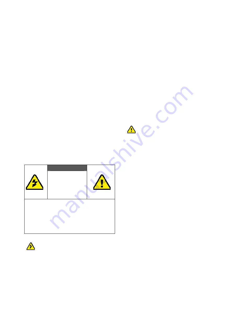
WARNING!


RISK


OF


ELECTRICAL


SHOCK


DO


NOT


OPEN


WARMING:


TO


REDUCE


THE


RISK


OF


ELECTRICAL


SHOCK

DO


NOT


REMOVE


THE


COVER


NO


USER

SERVICEABLE


PARTS


ARE


INSIDE


REFER


SERVICING


TO


QUALIFIED


PERSONNEL


Danger:


Be


careful


with


electricity.


z


Power


to


the


units


must


be


switched


off


before


any


work


is


undertaken,


such


as


any


AV


device


connection


or


TV


connection.


z


Power


outlet:


To


prevent


electric


shock,


make


sure


to


use


the


appropriate


AC


adapters


as


power


supply


to


the


transmitter


and


the


receiver.


z


Power


cord:


Be


sure


the


power


cord


is


routed


so


that


it


will


not


be


stepped


on


or


pinched


by


heavy


items.


z


Power


overloading:


Avoid


overloading


electrical


outlets


or


extension


cords


which


otherwise


could


result


in


electric


shock


or


fire.


z


Lightning:


Disconnect


the


product


from


the


power


source


if


it


is


left


unattended


for


a


long


period


of


time,


and


to


protect


the


product


from


lightning.


z


Always


disconnect


the


power


cord


from


the


power


outlet


when


you


are


not


using


your


Full


HD


Video


wireless


kit.


This


reduces


the


risk


of


electric


shocks


or


fire.


Warning


z


This


product


should


not


be


exposed


to


dripping


or


splashing.


No


object


filled


with


liquids,


such


as


vases,


should


be


placed


on


the


product.


z


Object


Entry:


To


avoid


electric


shock,


never


stick


anything


in


the


slots


on


the


case


or


remove


the


cover.


z


Place


receiver/transmitter


on


a


flat,


hard


and


stable


surface


z


Ventilation:


Do


not


block


the


ventilation


slots


on


the


receiver/transmitter


or


place


any


heavy


object


on


the


top


cover.


Blocking


the


air


flow


could


damage


the


receiver.


Arrange


components


so


that


air


can


flow


freely


around


the


receiver.


Ensure


that


there


is


adequate


ventilation


if


the


receiver


is


placed


in


a


stand.


Put


the


receiver/transmitter


in


a


property


ventilated


area,


away


from


direct


sunlight


or


any


source


of


heat.


z


Water


Exposure:


To


reduce


the


risk


of


fire


or


electric


shock,


do


not


expose


the


receiver/transmitter


to


rain


or


moisture.


z


This


is


indoor


solution.


z


Our


company


has


the


right


to


modify


this


document


without


any


notice.


Summary of Contents for Air SyncHD/DX

Page 1: ... 0 ...

Page 2: ...ANSMITTER 12 STEP2 SETUP THE BV 2822R RECEIVER 12 STEP3 SETUP THE IR BLASTER EXTENDER CABLE AND IR SENSOR EXTENDER CABLE 14 STEP 4 BOOT UP THE BV 2822T AND BV 2822R 15 STEP 5 WIDE MODE USAGE 19 STEP 6 MOUNTING THE BV 2822R RECEIVER TO THE WALL 21 4 TROUBLESHOOTING 22 5 SUPPORTED RESOLUTION 24 6 AUDIO BIT RATE SUPPORT 25 7 PRODUCT SPECIFICATION 26 ...

Page 3: ...cord is routed so that it will not be stepped on or pinched by heavy items z Power overloading Avoid overloading electrical outlets or extension cords which otherwise could result in electric shock or fire z Lightning Disconnect the product from the power source if it is left unattended for a long period of time and to protect the product from lightning z Always disconnect the power cord from the ...

Page 4: ...nput current up to and including 16 A per phase EN 61000 3 3 Electromagnetic compatibility EMC Part 3 Limits Section 3 Limitation of voltage changes voltage fluctuations and flicker in public low voltage supply systems for equipment with rated current 16 A per phase and not subject to conditional connection EN 55024 Information technology equipment Equipment Immunity characteristics Limits and met...

Page 5: ...ements Use of this device in a manner inconsistent with this manual could lead to excessive RF exposure conditions z The following regulatory and Safety notices must be published in documentation supplied to the end user of the product or system incorporating an adapter in compliance with local regulations Host system must be labeled with Contains FCC ID XXX XXXXX FCC ID displayed on label System ...

Page 6: ... compliance z Outdoor operations in the 5150 5250MHz 5600 5650MHz band are prohibited z This device has no Ad hoc capability for 5250 5350MHz and 5470 5725MHz z Outdoor operations in the 5470 5725MHz band are prohibited This device could not be used in the 5600 5650MHz z The device not operation in 5600 5650MHz CAUTION of System on Canada region z Industry Canada regulatory information Operation i...

Page 7: ...ivers uncompressed 1080p full HD video and audio content to your existing HDTV set wirelessly It operates the transmission in 4 9 GHz 5 9 GHz frequencies and it can adjust its communication frequency automatically in case of interference from another RF system With built in Omni directional antennas it can transmit uncompressed video content to 20 meters 66 feet LOS Line of sight with no latency B...

Page 8: ...in blue when the power is on and turns red in standby mode Y Source Selection Button Press to switch between the various inputs of the transmitter The one of six LED indicators next to this button is lit in solid blue to show current input you switch Press this button to cycle through connected sources in sequence Source 1 4 are HDMI input Source 5 6 are Component input with L R Audio input ...

Page 9: ...HDMI IN Connect Transmitter to High definition audio video devices that have an HDMI port using a provided HDMI cable BV 2822T supports 4 HDMI in for user selection Component Video IN Audio L R IN Connect to audio video devices with Component jack YPbPr and Audio L R such as DVD player Blu Ray Player or Cable Set Top Box BV 2822T supports 2 Component in with audio L R for user select it DC IN For ...

Page 10: ...laced near your HDTV set so that you can easily operate and control your AV equipment connected to BV 2822T by pointing the remote control to the TV instead of the AV equipment Y HDMI OUT For connecting the HDTV set via an HDMI cable Z DC IN For connecting the BV 2822R power adapter Note Make sure you have connected the BV 2822R correctly to your HDTV set with an HDMI cable and have selected the c...

Page 11: ... 1 2 When BV 2822T s LED is in purple listen mode loopthrough on and BV 2822R s LED in red Point the remote at the BV 2822R and press POWER to connect it to BV 2822T When a connection is established both POWER LEDs should be in solid blue INFO Press this button to display related information Please refer to page 10 for more information Press once to display the current status Press again to exit O...

Page 12: ...Displayed HDMI1 CH 1 WIDE Off 1280x1024 Standby Mode Loop thru On Y Press the INFO button 1 Press the INFO Button on the RCU and Signal Quality Source Channel WIDE mode status and resolution will be displayed for user reference OSD Displayed HDMI1 CH 1 WIDE Off 1280x1024 INFO Exit OSD SOURCE Tune CLK Phase 2 During the OSD display press SOURCE key to change the clock and phase alignment only avail...

Page 13: ...onds to switch Channel manually HDMI1 CH 8 WIDE Off 1280x1024 Press again to change Channel Press the WIDE button of RCU for longer distance transmission of audio video contents 1 Press once for current WIDE mode status displayed on the OSD Default is disable HDMI1 CH 1 WIDE Off 1280x1024 Press again to switch WIDE mode 2 Press WIDE button again within 5seconds to switch WIDE mode status OSD Displ...

Page 14: ...r IN connectors of the BV 2822 and corresponding COMPONENT Y Pb Pr OUT connectors on your High Definition devices The ZWD 2822T has two Component inputs for general audio video device connection 3 Connect the BV 2822T s transmitter HDMI OUT to the HDTV set s HDMI IN port with an HDMI cable for the loop through output 4 Connect the supplied power adapter to the DC IN jack of the BV 2822T and a wall...

Page 15: ...jector Press the Source Input button of your TV s remote to select the appropriate HDMI video input 2 Connect the supplied power adapter to the DC IN jack of the BV 2822R and a wall socket The LED indicator in the POWER button lights up in solid blue when the BV 2822R is connected to the power mains ...

Page 16: ...hould be close to the front panel of your High Definition device usually behind a dark and sometimes reddish plastic window When the IR blaster cable is connected it relays infrared command from your remote control to the device Users can control their AV devices by pointing their remote control to the TV instead of to their AV equipment 2 If your connected device will be out of the direct line of...

Page 17: ...lugged into the electrical outlet the BV 2822 will be turned on automatically 3 If the BV 2822 is in standby mode and the Loopthrough connection is off both POWER LEDs of the transmitter and receiver are lit in red press POWER on both BV 2822T and BV 2822R to turn them on It will take about 1 minute for the system to boot up ...

Page 18: ... 2822R Note During this period BV 2822T will enter Standby mode and turn off Loop thru display when press the POWER button of transmitter or press the POWER key of RCU point to transmitter 5 During the warm up the POWER LED will blink in blue until the signal link between the BV 2822T and the ZWD 2822R is established Ensure your TV set or projector is in HDMI input mode and is already powered on ...

Page 19: ... different channels Note A Changing the BV 2822 to a different wireless channel B Channel Number Indicating the Wireless Frequency 1 Enter the wireless RF channel adjustment mode 2 Changes to the next available RF wireless channel 3 Exit the wireless RF channel adjustment mode Method Press the CHANNEL button on the Remote Control Unit RCU for current channel status display Press the CHANNEL button...

Page 20: ... V 4 5260 5700 X X 5745 V 5 5765 V 6 5785 V 7 5805 V 8 5825 V 9 Note A Gray background indicates the DFS region B All channels are Limited to in door use C Unused Weather Satellite Channels on DFS i WIDE mode OFF Center Frequency 5590MHz 5630MHz ii WIDE mode On Center Frequency 5600MHz 5620MHz 5640MHz 8 TRANSMITTER RECEIVER Status Indicator on LED and OSD LED indicator status light on the front pa...

Page 21: ...tion is recognized Transmission is available with stable RF signal Note A Make sure your high definition audio video devices connected to the BV 2322T has already been powered on B Warming up or source switching time should take approximately 20 30 seconds if the operation is in normal condition C If the RF connection exceeds 30sec without the link established the link might be lost or the transmi...

Page 22: ...1080i or below HD video transmission is available when enabling the Wide mode OSD shows WIDE On Please shorten the distance and disable the Wide mode OSD shows WIDE Off if full HD 1080p 60Hz content transmission is desired ...

Page 23: ...tive position of the main holes and attach this paper on wall 2 Drill pilot holes 3 Insert the supplied two Anchors into the wall 4 Insert two screws into the anchors Leave 1 8 length for mounting the Transmitter or receiver 5 Place BV 2822R main holes over the protruding screws and slide down into position ...

Page 24: ...LED OSD shows No Supported Format Ensure your video resolution and frame rate is recognized supported and within the transmission range Connect the source device to your TV to check and modify the video format compatibility Check if your video resolution with HDMI input from your device is set among 1080p 1080i 720p 576p or 480p POWER LED in Solid Blue STATUS LED Flash Quickly OSD shows No Signal ...

Page 25: ...pported resolution Some resolution can t be supported on WIDE mode on IR Blaster can t control Source device Check where is IR sensor of Source device Make sure IR Blaster sensor is close and straight to Source device s IR sensor Please refer Chapter 3 step 3 for reference setup Change IR Blaster frequency to meet Source device s requirement Please continue pressing Source key on the top of Receiv...

Page 26: ...x480i 60Hz 480i YES For Component Input only 640x480p 59 94 60Hz YES YES 720x480p 59 94Hz YES YES 720x480p 60Hz 480p YES YES 720 1440 x576i 50Hz 576i YES For Component Input only 720x576p 50Hz 576p YES YES 1280x720p 50Hz YES YES 1280x720p 59 94 60Hz 720p YES YES 1920x1080i 50Hz YES YES 1920x1080i 59 94 60Hz 1080i YES YES 1920x1080p 50Hz YES n a 1920x1080p 59 94 60Hz 1080p 60 YES n a Secondary CEA ...

Page 27: ...z sampling rate as below 2 8 channel PCM 32KHz 44 1KHz 48KHz 96KHz 16 bits YES YES YES YES 24 bits YES YES YES YES Analog Audio from Base Band audio L R inputs Convert to 2 channel by fixed 24 bits sample with sampling rate 48KHz over Wireless High Definition Interface transmission Analog Audio Input Input Level 500mVrms typ 10 27KΩ load Type Stereo R L channel ...

Page 28: ...0V AC in 5V 3A DC out Power Adaptor Operating Temperature 0 40 C Interfaces BV 2822T BV 2822R Component Input Two Sets of RCA Connectors Analog Audio L R Input Two Sets of RCA Connectors HDMI Input Four Type A A V Interfaces HDMI Output One Loop through One Type A IR Sensor YES YES IR Sensor Extender 2 5mm Jack Control Signal Interfaces IR Blaster Extender 2 5mm Jack Power Power Input 5V DC Jack 5...

Page 29: ...27 ...

Page 30: ...0 ...

Reviews: