


9
Note:
1.
When
the
system
is
in
active
mode,
press
POWER
key
on
the
RCU
pointing
to
transmitter
or
on
the
top
of
transmitter,
then
both
the
transmitter
and
the
receiver
will
enter
“Standby
mode”
(RF
disconnected;
LED
lit
in
red)
and
Loop
‐
through
display
and
the
2
nd
display
will
be
off.
2.
When
the
system
is
in
active
mode,
press
POWER
key
on
the
RCU
pointing
to
receiver
or
on
the
top
of
receiver,
then
the
transmitter
will
enter
“Listen
mode”
(RF
disconnected;
POWER
LED
lit
in
purple)
and
the
2
nd
display
(the
display
attached
to
the
receiver)
will
be
off
but
Loop
‐
through
display
(the
display
attached
to
the
transmitter)
will
keep
on.
3.
The
“Standby”
mode
(Power
LED
lit
in
red
)
consumes
90%
less
of
the
power.
User
has
to
press
power
key
on
top
cover
of
both
transmitter
and
receiver
or
press
POWER
key
pointing
to
transmitter
and
receiver
both
to
resume
to
“Active
mode”.
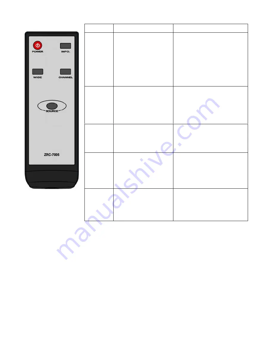
Button
Function
Description
Operation
POWER
Press
to
turn
the
BV
‐
2822
Transmitter/
Receiver
on/off.
See
below
for
Note
1
&
2.
When
BV
‐
2822T’s
LED
is
in
purple
(listen
mode;
loopthrough
on)
and
BV
‐
2822R’s
LED
in
red:
Point
the
remote
at
the
BV
‐
2822R
and
press
POWER
to
connect
it
to
BV
‐
2822T.
When
a
connection
is
established,
both
POWER
LEDs
should
be
in
solid
blue.
INFO.
Press
this
button
to
display
related
information.
Please
refer
to
page
10
for
more
information.
Press
once
to
display
the
current
status.
Press
again
to
exit
OSD.
When
using
component
video
connection,
this
button
can
be
used
to
adjust
clock
and
phase
alignment.
SOURCE
Press
this
button
to
switch
audio/video
sources
connected
to
the
BV
‐
2822T.
Press
to
go
to
the
next
input
source.
Users
can
see
the
current
setting
on
the
OSD.
CHANNEL
Press
this
button
to
change
wireless
channels
manually
if
the
user
experiences
video
noise.
Press
once
to
display
the
current
"Channel"
status.
Press
again
within
5
seconds
to
switch
to
another
channel,
and
the
channel
number
will
be
displayed
on
the
OSD.
WIDE
Press
this
button
to
distance;
up
to
100
feet
under
line
of
sight.
(1080i
content
only)
Press
this
button
to
enable
or
disable
WIDE
mode.
Press
again
within
5
seconds
to
enable
WIDE
mode,
and
the
status
will
be
displayed
on
the
OSD.
(Default
=
WIDE
off)