


Faultfinder
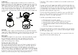
Installation
A competent person must always carry out the installation of this product in
accordance with these instructions. The installation must comply with the
current local water company regulations.
The following points should always be considered when carrying out an
installation
1) Care must be taken to prevent any risk of injury or damage to persons or
property.
2) The product has integral isolation for servicing the unit, further isolation
could be included if considered necessary.
3) To eliminate pipe debris entering the valve the system must always be
thoroughly cleaned and flushed particularly if it is new, or extensive
modification has taken place. The product must never be used without
the in line filters fitted; failure to fit the filters may invalidate the
guarantee.
4) The fitting is supplied with a single check valve in each inlet; it should
be fitted so that the relevant air gap specified in the water regulations is
achieved above the spillover level of the basin or trough.
5) The surface to which the unit is to be fixed needs two holes minimum
23mm diameter maximum 30mm diameter at 150mm to 200mm centres
(the tails are eccentric giving variable centres)
6) If fitted in a health care environment the relevant Health Technical
Memorandum must be consulted to ensure correct positioning of the
outlet in relation to the basin or trough.
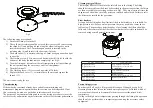
7) The unit is supplied suitably configured for fitting onto a high pressure
system if a low pressure system is to be used the flow limiters (item 16
and 17) must be removed see servicing for method.
8) When viewed from the front and the unit is connected to the supplies the
Hot supply must be connected to the left hand inlet and the cold to the
right hand inlet.
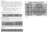
Inlets
15mm Compression or ½” BSP
Male Iron
Outlet
24mm Flow Straightener
Minimum pressure drop through fitting for correct
mixing
0.1 bar
Maximum Pressure Drop Through Fitting for Correct
Mixing
5bar
Maximum static pressure to be applied to fitting
10bar
Mixed water temperature variation with nominal
variations of supply parameters
± 2ºC
Factory set maximum mixed water temperature
43ºC
Maximum hot supply temperature
80ºC
Maximum pressure loss ratio without flow limiters
5:1
Fault
Cause
Repair
No or reduced flow and/or
fluctuating temperature
One or both isolating valves not
fully open
Flow limiters incorrectly fitted
Inlet pressures below specified
values
Supply pipes blocked
Waterways in tap blocked
Supply pressures unequal
Open both valves fully
Check information and refit
correctly
Alter system to increase supply
pressures
Rectify system fault
Clear debris or call service
department
Check maximum pressure
differential, and check if flow
limiters correctly fitted
Maximum outlet temperature
too hot
Maximum mixed water
temperature incorrectly set
Reset temperature see
calibration section
Maximum outlet temperature
too cold or runs cold after a
short time
Maximum mixed water
temperature incorrectly set
Hot water temperature too low
Reset temperature see
calibration section
Increase water temperature by
adjusting storage temperature or
power input to the system
Mixed water flow too high
Flow limiters incorrectly fitted
See section on flow limiters
Only hot or cold water at outlet
Maximum mixed water
temperature incorrectly set
Inlet supplies reversed
Reset temperature see
calibration section
Re pipe supplies
Tap will not shut off or dripping
Seal damaged or worn
Scale build up in body
Inlet pressure above maximum
static pressure rating
Renew seals from spare parts kit
Service and descale fitting
Reduce pressure possibly by
fitting reducing valve
No thermostatic fail safe
Inlet temperatures outside
specification
Debris trapped in mechanism or
mechanism jammed
Inlet supplies reversed
Reset boiler or recirculation
temperatures
Strip and clean unit or call the
service dept
. Re pipe supplies