background image

Troubleshooting

Network Problems

Under normal operation, you should be able to “ping” the network address of the Bridge and receive
a response. If this fails, run through the following checklist to help you identify the problem.

• Make sure that the power LED on the Bridge is illuminated.

• Ensure that the Ethernet cable is plugged in at both ends.

• Note the status of the LEDs positioned within the Ethernet connector - make sure that the

Link present

LED is illuminated. If it is not, check with your Network Administrator.

• If you are using a Bridge with two Management ports and only one network cable, try using

the other network address and/or the other Management port.

• If the Bridge is transferring large amounts of data, then the response from the web interface

may seem slower than usual as the process that controls the web interface has the lowest
priority for Network and CPU resources.

• If you can “ping” the Bridge but the web interface fails to appear, check the settings within

the web browser you are using. If you are directly connected to the Bridge then any proxy
settings will require adjustment and may require you to contact your administrator.

• Ensure you are using the correct network address and netmask. See Appendix A:

Accessing

the Bridge from Windows using a static IP Address

.

• Scan the network using the

LAN Scan

utility to find all the Bridge’s connected to the network

in case the network address is different than what was expected. See Section 8.3:

Lost IP

Address

.

If none of the above resolves your problem, then after consulting with your Network Administrator,
please contact support. See Appendix B:

Useful Links

for information on how to contact Bridgeworks

Support.

Device Related Problems

Once the Bridge has finished booting up, and the target devices have finished initialising, these
devices should be available on the host machine. After checking that you have correctly configured
the initiator, run through the following checklist to help you identify and solve the problem.

• Ensure that the devices are powered on and are ready - some libraries can take 5 minutes or

more before they are ready and appear on the Bridge. The power up status of libraries are
usually displayed on the front panel.

• Ensure that the cables between the Bridge and the devices are connected.

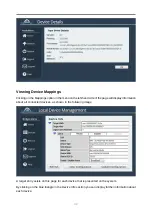
• Connect to the Bridge via the web interface and check that devices are present in the

Local

Device Management

page, and that they are enabled. See Section 6.2:

Viewing Device

Mappings

for checking device information.

46

Summary of Contents for Tamar FCSAS102800

Page 1: ...Tamar FCSAS102800 FC to SAS Bridge User Manual Eli v4 05 204 Bridgeworks Unit 1 Aero Centre Ampress Lane Ampress Park Lymington Hampshire SO41 8LW Tel 44 0 1590 615 444 Email support 4bridgeworks com ...

Page 2: ...o between your network access point and the Bridge This should be marked as certified to Cat 5e and have an RJ45 style connector at the Bridge end SAS Cable The Bridge uses a Mini SAS style connector also known as an iPASS or 8088 connector with 4 SAS connections per port You will require a SAS cable that supports this connector at the Bridge end and the type of connector your peripheral device su...

Page 3: ... 2 4 Connecting the Power Supply 13 3 Using the Web Interface 15 3 1 Browsers 15 3 2 Connecting to the Web Interface 15 3 3 Management Console Home screen 17 4 Bridge Configuration 18 4 1 Network Connections 18 4 1 1 Global Network Configuration 19 4 1 1 1 Hostname 19 4 1 1 2 Enable IPv6 19 4 1 2 Network Interfaces 19 4 1 2 1 Setting the MTU 20 4 1 2 2 Setting the IP Address 21 4 1 2 3 Committing ...

Page 4: ...d Devices 31 6 2 Viewing Device Mappings 32 7 Bridge Maintenance 33 7 1 System Information 33 7 2 System Log 34 7 3 Load Save Configuration 35 7 3 1 Saving the Configuration to Disk 35 7 3 2 Restore to Factory Defaults 36 7 4 Firmware Updates 36 7 5 Diagnostics 38 7 6 Task Scheduler 38 7 6 1 Adding Tasks 39 7 6 2 Removing Editing Tasks 39 7 6 3 Task Wizard 41 7 6 3 1 Action Email Performance Stati...

Page 5: ... Lost IP Address 47 8 3 1 Downloading LAN Scan 47 8 3 2 Using LAN Scan 47 Appendix A Accessing the Bridge from Windows using a static IP Address 49 A 1 Windows Server 2003 49 A 2 Windows Vista Server 2008 or 7 52 Appendix B Useful Links 55 Appendix C Technical Specifications 56 5 ...

Page 6: ...Introduction Thank you for purchasing the Bridgeworks Tamar FCSAS102800 Fibre Channel to SAS Bridge 6 ...

Page 7: ...represents a warning Care must be taken and the warning should be read thoroughly SCSI Target Device A SCSI device is a device that is connected to the SCSI bus that can be accessed by the Server Each device on the SCSI bus has a Unique ID number in the range 0 15 Note By convention ID 7 on the SCSI Bus is reserved by the Server s Host Bus Adaptor Logical Unit Number LUN Each SCSI device on the SC...

Page 8: ... technician To prevent electric shock do not remove the cover There are no user serviceable parts inside The power cord is used as a disconnection device To de energise the equipment disconnect the power cord Do not use the equipment where it can get wet Protect equipment from liquid intrusion If your equipment gets wet disconnect power to the equipment and to any attached devices If the Bridge is...

Page 9: ...ct Certain models will use a Small Form factor Pluggable SFP Transceiver module for connection to an optical network These devices may use a Class 1 Laser device it is important that you do not stare into the Laser beam 9 ...

Page 10: ... Gigabit It is not necessary to specify which network type you are connected to as the FCSAS102800 will automatically select the correct network speed The connection to the management Ethernet network can be found at the back of the FCSAS102800 labelled MGMT A and MGMT B To connect the FCSAS102800 to the management Ethernet network insert a Cat 5E cable or better into one of the MGMT ports at the ...

Page 11: ...However devices that operate at slower speeds 1 5 Gbits s and 3Gbits s can still be connected to this SAS bus The Bridge will automatically negotiate with these devices to obtain their optimal operating speed upon power up Each SAS wide port can support up to 4 PHYs Connect the SAS cable s to the Bridge as shown below ensuring that connector is the correct way up 11 ...

Page 12: ... first powered up To connect to the Fibre Channel network a Small Form factor Pluggable SFP interface module must be inserted into the SFP receptacle at the back of the FCSAS102800 as shown in the following image Note Only use SFP transceivers that meet or exceed the following standards EU IEC EN 60825 1 North America FCC CDRH The following Optical Fibre cables may be used Multi mode Optical Fibre...

Page 13: ...ote Before powering up the FCSAS102800 ensure that all peripherals are properly connected and are powered up and that you have connected a Management port to your network To turn on the FCSAS102800 push the switch on the opposite side to the power connector The following image shows the switch Whenever the FCSAS102800 is powered on the switch will be illuminated in the colour green and system fans...

Page 14: ...14 ...

Page 15: ...ose to use a browser that is not in the list of supported browsers Bridgeworks cannot guarantee the behaviour of the Bridge s functionality Connecting to the Web Interface Note DHCP is enabled by default on the management interface The default hostname is bridgeworks The default static IP address of the management interfaces are Management A left hand interface 10 10 10 10 Management B right hand ...

Page 16: ...or help with accessing the Bridge web interface without DHCP From within your web browser connect to the Bridge s web interface using default hostname or IP address of a connected management interface Once you have connected to the web interface on the Bridge you will see the entry page shown below Enter and confirm the new web interface password to be presented with the login screen The password ...

Page 17: ...r logout of the web interface The Home link may be used from any page to return to the Home screen Note Whenever a Reboot command is issued it may take several minutes for the Bridge to become accessible again The Support link will open up a new tab in your browser at the Bridgeworks website support page The Help is contextually aware of which page you are currently viewing on the web interface an...

Page 18: ...ervice settings Network Connections This configuration page allows the administrator to configure network interface settings and view network statistics From the Home screen select the Network Connections icon under the Bridge Configuration section The web interface will display the following 18 ...

Page 19: ...enabled management interface Enable IPv6 Selecting the Enable IPv6 checkbox will enable the Bridge to use IPv6 addresses As with IPv4 you can either choose to use DHCP or assign a static IPv6 address Network Interfaces This section displays each network port present on the Bridge along with its current status link speed and hardware identifier MAC address To change the settings of a specific netwo...

Page 20: ...mbo frames use a smaller jumbo frame size Consult your networking equipment documentation for additional instructions Important Some networking switches require you to specify the size of the jumbo frame MTU when enabling as opposed to a simple enable command On these switches it might be required to add the necessary bytes needed for the frame header to the MTU size you specify in the Bridge s po...

Page 21: ...you can choose to use DHCP to automatically assign an IPv6 address or you can set a static IPv6 address If you choose to assign a static IPv6 address you will also need to supply the IPv6 subnet mask in slash notation e g fe80 1234 ffff fffe 5678 64 Note DHCP is enabled by default on management interfaces Important If DHCP is enabled please ensure your DHCP server is set to automatically update th...

Page 22: ...tion radio button and click Save You will be logged out of the Bridge s web interface and further transactions with the web interface will use SSL TLS encryption Note By default an HTTPS certificate key will be generated when HTTPS is enabled You can use your own certifcate key pair by selecting files to upload with the file picker buttons You may upload the key pair as two separate files or one c...

Page 23: ...The web interface will display the following 23 ...

Page 24: ... Trigger Event Log Level The minimum log level to trigger an email Events of higher urgency than the selected level will also trigger an email The available levels are in descending order of urgency Critical Example The Bridge is running at non recommended temperatures Error Example A device attached to the Bridge has been disconnected Warning Example An invalid configuration file was uploaded Con...

Page 25: ...e SMTP server May be blank depending on your server s configuration SMTP Password Password credential to be used to send emails from the SMTP server May be blank depending on your server s configuration Click Save to apply any changes made to the SMTP configuration 25 ...

Page 26: ...will then display the following The icons displayed in the Fibre Channel Interfaces section show the current state of each Fibre Channel Port The green or red light in the icon display whether the port is up or down This is also shown in text next to each icon with the negotiated Fibre Channel speed and the selected topology The port WWN is also shown next to each icon Clicking on an icon will dis...

Page 27: ...box Check this to enable the link onto the Fibre Channel Storage Area Network SAN The Link Speed drop down menu allows you to select the Fibre Channel network speed In most cases this can be kept as Automatic The Topology drop down menu allows you to force the Fibre Channel topology when the Bridge logs on to the Fibre Channel SAN 27 ...

Page 28: ...ERP Clicking Save will save the configuration to memory for use at the next reboot Connected Hosts To list which hosts are connected to the Bridge select a port under Fibre Channel Interfaces then select the icon labelled View all the Fibre Channel initiators which have logged into this target port The following will then be displayed Port Map The Port Map page allows the administrator to assign d...

Page 29: ...nnel target ports so that any connected host will see all devices Manual will allow the administrator to manually assign which target devices appear on which Fibre Channel port Important When Automatic port mapping is selected LUN order is not guaranteed to be the same between reboots Selecting Manual will show the following 29 ...

Page 30: ...ogical Unit drop down menu 2 Select which Fibre Channel Port you wish the device to appear on 3 Select the LUN you wish the device to have on the selected Fibre Channel Port 4 Click the Add Assignment button at the bottom of the panel The example above shows 1 device assigned to Port 1A with the LUN 0 30 ...

Page 31: ...hed Devices From within the Home screen of the web interface select the SCSI Device Management icon under the Devices and Protocols section The web interface will then display the following You will be presented with a list of all the devices connected to the FCSAS102800 Clicking on a device will open a page displaying more information about the device as shown below 31 ...

Page 32: ... the page will display information about all connected devices as shown in the following image A target entry exists on this page for each device that is presented on the system By clicking on the blue triangle in the Device Info section you can display further information about each device 32 ...

Page 33: ...age allows the administrator to view the performance of the Bridge From the Home screen select the System Information icon from the Bridge Maintenance section The following page will be displayed In the Bridge Firmware Details section the following information is displayed Firmware Revision is the installed firmware revision level SAS Firmware Revision is the installed SAS binary revision level 33...

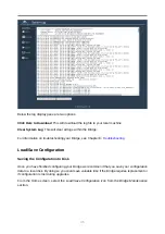
Page 34: ...mance in MB s CPU Utilisation This indicates the percentage of the time the CPU is occupied undertaking the management and scheduling the transfer of data between the two interfaces Memory Usage This indicates the percentage of memory used by all processes System Log This page displays the system log useful for diagnosing problems with the Bridge attached devices and connections From the Home scre...

Page 35: ...dge see Chapter 8 Troubleshooting Load Save Configuration Saving the Configuration to Disk Once you have finished configuring your Bridge we recommend that you save your configuration data to a local disk By doing so you could save valuable time if the Bridge requires replacement or if configuration is lost during upgrades From the Home screen select the Load Save Configuration icon from the Bridg...

Page 36: ... the upload button and the new configuration data will be uploaded Once the configuration file is uploaded a reboot is required Restore to Factory Defaults By clicking on this button all the parameters will be set back to the factory defaults This includes IP address hostname and passwords This option is useful to protect sensitive information if a Bridge appliance is ever returned for maintenance...

Page 37: ...ware Updates page allows the administrator to load new firmware onto the Bridge From the Home screen select the Firmware Updates icon from the Bridge Maintenance section The following page will be displayed Once you have downloaded the new firmware to your local machine 1 Click on the Browse button to locate the file you have downloaded from our website 2 Click on the Update button to start A prog...

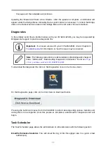
Page 38: ...on on how the issue may be resolved Note The following instructions are demonstrated in the Bridgeworks Support Video WANrockIT Downloading Diagnostic Information found at https www youtube com watch v 8RZXFGCy3ZU To download the diagnostic file click on the Diagnostics icon on the Home screen On the Diagnostics page click on the Click Here to Download button Pressing the button will cause the FCS...

Page 39: ...n The web interface will now display the following Adding Tasks Tasks can be added by clicking on the Add New Scheduling Task button which will start the task wizard Removing Editing Tasks If you already have some tasks added they will be listed in the Scheduled Tasks window as shown 39 ...

Page 40: ...cking on a task will expand it as shown Clicking the Remove button will remove the task from the task scheduler Clicking the Edit button will start the task wizard for the task allowing it to be edited 40 ...

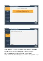
Page 41: ... navigate you to the next section of the wizard Previous If present this button will navigate you to the previous section of the wizard Note The currently active section of the wizard will be highlighted in orange on the left hand side Action Email Performance Statistics On the Action section of the wizard enter the recipient email s separating multiple emails with either commas or semi colons Imp...

Page 42: ...e event The options are Once This means the action will be performed at the specified time and not repeat Daily This means the action will be performed every day at the specified time Weekly This means the action will be performed on specified days every week at the specified 42 ...

Page 43: ...boxes Each day will have its own checkbox as shown Start Date On the Start Date section of the wizard you can pick the starting date and time for the new task Enter a time into the Time for the first trigger box and select your start date using the calendar The selected date will be marked with a red cross 43 ...

Page 44: ...e wizard you can pick the end date for the new task You can either select the Ongoing Event checkbox for a task that should run until cancelled or select a date using the calendar The selected date will be marked with a red cross Summary 44 ...

Page 45: ...ary section of the wizard a brief description of the task will be displayed If you are happy with this task click the Save button to add the task to the task scheduler Saving will automatically close the wizard 45 ...

Page 46: ... Ensure you are using the correct network address and netmask See Appendix A Accessing the Bridge from Windows using a static IP Address Scan the network using the LAN Scan utility to find all the Bridge s connected to the network in case the network address is different than what was expected See Section 8 3 Lost IP Address If none of the above resolves your problem then after consulting with you...

Page 47: ... and for checking the number of Bridgeworks devices on a network Downloading LAN Scan The utility can be downloaded from http www 4bridgeworks com support download firmware LAN Scan may also be provided on the CD accompanying your FCSAS102800 Using LAN Scan LAN Scan is a command line utility available for Windows The downloaded file is in zip format and contains the files lanscan exe and lanscan b...

Page 48: ...48 ...

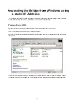
Page 49: ... 2003 If your computer is running Windows Server 2003 follow the instructions below From the Desktop or Start menu select My Computer In the My Computer window select Network and Dial up Connections positioned in the bottom left hand corner From within the displayed Network and Dial up Connections select the interface connection that will be used to connect to the Bridge in this example we have se...

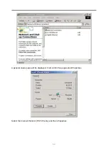
Page 50: ...A general status page will be displayed From within this page select Properties Select the Internet Protocol TCP IP entry and then Properties 50 ...

Page 51: ...ake a note of your current set up then 1 Click Use the following IP Address 2 Enter 10 10 10 11 into the IP Address field 3 Enter 255 255 255 0 into the Subnet Mask field 4 Finally click the OK button 51 ...

Page 52: ...reconnect to the Bridge Windows Vista Server 2008 or 7 If your computer is running Windows Vista or 7 follow the instructions below From the Start menu select Control Panel From the Control Panel select the Network and Internet link followed by the Network and Sharing Centre link Click on Local Area Connection 52 ...

Page 53: ...A general status page will be displayed From within this page select Properties Select the Internet Protocol Version 4 TCP IPv4 entry and then Properties 53 ...

Page 54: ...Address 2 Enter 10 10 10 11 into the IP Address field 3 Enter 255 255 255 0 into the Subnet Mask field 4 Finally click the OK button Note Once you have completed the initial set up of the Bridge return your computer to the original settings and reconnect to the Bridge 54 ...

Page 55: ...geworks Support If you continue to experience problems with the FCSAS102800 please contact support at http www 4bridgeworks com support Bridgeworks Support Videos These videos will guide you through some of the instructions found in this manual https www youtube com user SANSlide Product Manuals The latest product manuals can be found at http www 4bridgeworks com support user manuals 55 ...

Page 56: ...nmental Operational temperature 10 C to 35 C Non operational temperature 20 C to 60 C Humidity 8 85 non condensing Network Management Interface No of interfaces 2 Physical RJ45 8P8C Speed Auto sensing 10 100 1000Mb s Standards IPv4 IPv6 NTP SNMP DHCP SAS Interface No of ports 2 Physical SFF 8088 External mini SAS Channels per port 4 Speed Auto sensing 1 5 3 6Gb s Protocol SAS 2 0 Fibre Channel Int...

Reviews: