Bridgeworks Oresund FCE102200 User Manual Download Page 25

Simple Network Time Protocol

SNTP is a protocol for synchronising the clock of computer systems. This feature is critical if you
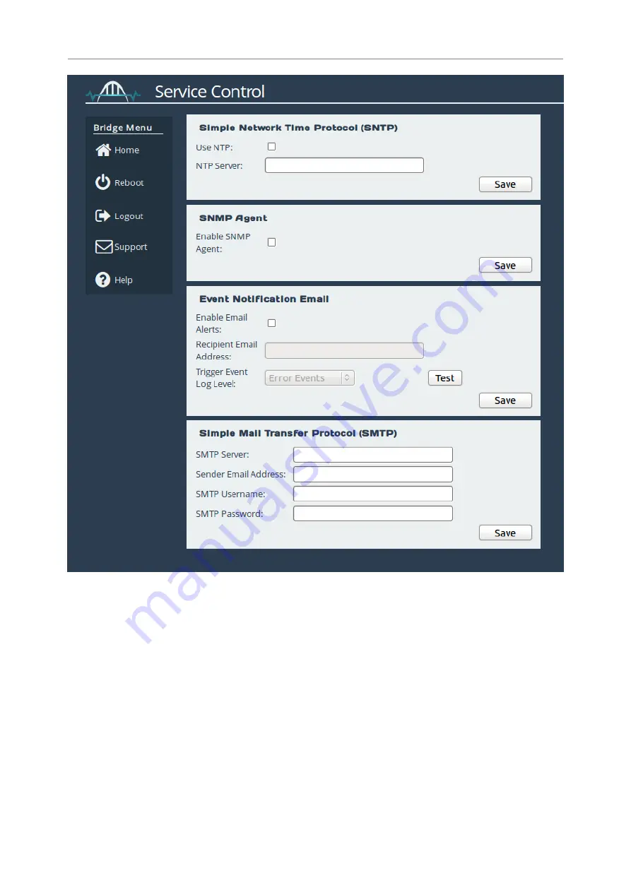
are planning on using the scheduler or useful when viewing the logs to determine when an event
occurred. Refer to Section 8.2:

System Log

for more information.

To enable SNTP, select the

Use NTP

checkbox and enter the IP address for the NTP Server. Then

click

Save

.

Event Notification Email

The Gateway can notify a systems administrator when events of a certain urgency occur in the

Gateway log. Before this can be done, SMTP settings must be saved. Refer to Section 4.3.3:

25

Summary of Contents for Oresund FCE102200

Page 1: ...resund FCE102200 FC to iSCSI Gateway User Manual Eli v4 05 204 Bridgeworks Unit 1 Aero Centre Ampress Lane Ampress Park Lymington Hampshire SO41 8LW Tel 44 0 1590 615 444 Email support 4bridgeworks co...

Page 2: ...y end 10Gb Ethernet Cable Depending on the configuration you have purchased you will require at least one cable from either FCE102200RM OPT Multi mode Optical Fibre Cable SFP Multi mode Optical Fibre...

Page 3: ...i mode Optical Fibre Cable SFP 11 2 2 2 Using a Copper Interface Cable SFP 12 2 2 3 Using a 10GBASE T Category 6 Cable RJ45 13 2 3 Connecting the Fibre Channel Interface 13 2 4 Connecting the Power Su...

Page 4: ...ons 27 5 1 Port Configuration 28 5 2 Connected Hosts 29 5 3 Port Map 29 6 iSCSI Initiator Configuration 32 6 1 Discovering an iSCSI Target 32 6 2 Removing an iSCSI Discovery Portal 36 6 3 Log On to an...

Page 5: ...e Statistics 48 8 6 3 2 Trigger 49 8 6 3 3 Start Date 50 8 6 3 4 End Date 51 8 6 3 5 Summary 51 9 Troubleshooting 53 9 1 Network Problems 53 9 2 Device Related Problems 53 9 3 Poor Performance 54 9 4...

Page 6: ...Introduction Thank you for purchasing the Bridgeworks Oresund FCE102200 Fibre Channel to iSCSI Gateway 6...

Page 7: ...o communicate with it With iSCSI devices both targets and initiators an extra level of identification in addition to the IP address is employed This is called the IQN The IQN includes the iSCSI Target...

Page 8: ...echnician To prevent electric shock do not remove the cover There are no user serviceable parts inside The power cord is used as a disconnection device To de energise the equipment disconnect the powe...

Page 9: ...t Certain models will use a Small Form factor Pluggable SFP Transceiver module for connection to an optical network These devices may use a Class 1 Laser device it is important that you do not stare i...

Page 10: ...SE T Gigabit It is not necessary to specify which network type you are connected to as the FCE102200 will automatically select the correct network speed The connection to the management Ethernet netwo...

Page 11: ...Multi mode Optical Fibre Cable SFP FCE102200RM TCX 1 Copper Interface Cable SFP Using a Multi mode Optical Fibre Cable SFP If you have purchased a 10Gb card with the SFP s already connected the follow...

Page 12: ...Cable SFP If you are using a copper based solution an SFP Direct Attached Copper DAC Twin Ax interface cable must be used the maximum supported length of which is a 5 meter passive cable To connect th...

Page 13: ...the back of the unit When the plug is in the correct position a click should be heard Connect the other side of the cable to your Ethernet network or device Connecting the Fibre Channel Interface Wit...

Page 14: ...Patch Cable LC up to 300 meters Multi mode Optical Fibre 50 125 OM4 Patch Cable LC up to 550 meters When the multi mode cables are inserted in to the SFP a click should be heard Connecting the Power S...

Page 15: ...d that you have connected a Management port to your network To turn on the FCE102200 push the switch on the opposite side to the power connector The following image shows the switch Whenever the FCE10...

Page 16: ...se to use a browser that is not in the list of supported browsers Bridgeworks cannot guarantee the behaviour of the Gateway s functionality Connecting to the Web Interface Note DHCP is enabled by defa...

Page 17: ...r help with accessing the Gateway web interface without DHCP From within your web browser connect to the Gateway s web interface using default hostname or IP address of a connected management interfac...

Page 18: ...logout of the web interface The Home link may be used from any page to return to the Home screen Note Whenever a Reboot command is issued it may take several minutes for the Gateway to become accessib...

Page 19: ...ervice settings Network Connections This configuration page allows the administrator to configure network interface settings and view network statistics From the Home screen select the Network Connect...

Page 20: ...nabled management interface Enable IPv6 Selecting the Enable IPv6 checkbox will enable the Gateway to use IPv6 addresses As with IPv4 you can either choose to use DHCP or assign a static IPv6 address...

Page 21: ...bytes of payload MTU Before enabling jumbo frames ensure that all the devices hosts located on the network support the jumbo frame size that you intend to use to communicate with the Gateway If you ex...

Page 22: ...ic IP The IP address netmask and gateway set in the corresponding fields will be used for this port The gateway field may be left blank The IPv4 netmask field must be specified in dotted decimal form...

Page 23: ...ting password into the Old Password field then enter the desired new password into the two following fields Then click Change Password Secure Connection To enable HTTPS select the Use an encrypted web...

Page 24: ...oad the key pair as two separate files or one combined file Service Control This configuration page allows the administrator to configure network services for the Gateway From the Home screen select t...

Page 25: ...determine when an event occurred Refer to Section 8 2 System Log for more information To enable SNTP select the Use NTP checkbox and enter the IP address for the NTP Server Then click Save Event Noti...

Page 26: ...a test email to the recipient email address addresses to confirm that the email configuration is working correctly Simple Mail Transfer Protocol SMTP This section allows an SMTP server to be configure...

Page 27: ...will then display the following The icons displayed in the Fibre Channel Interfaces section show the current state of each Fibre Channel Port The green or red light in the icon display whether the por...

Page 28: ...x Check this to enable the link onto the Fibre Channel Storage Area Network SAN The Link Speed drop down menu allows you to select the Fibre Channel network speed In most cases this can be kept as Aut...

Page 29: ...RP Clicking Save will save the configuration to memory for use at the next reboot Connected Hosts To list which hosts are connected to the Gateway select a port under Fibre Channel Interfaces then sel...

Page 30: ...nel target ports so that any connected host will see all devices Manual will allow the administrator to manually assign which target devices appear on which Fibre Channel port Important When Automatic...

Page 31: ...gical Unit drop down menu 2 Select which Fibre Channel Port you wish the device to appear on 3 Select the LUN you wish the device to have on the selected Fibre Channel Port 4 Click the Add Assignment...

Page 32: ...ateway requires two basic steps Discover iSCSI target s on the target portal Log on to the iSCSI target s The following sequence is repeated for each device you wish to connect to the iSCSI Gateway Di...

Page 33: ...Click on the Add button in the Discovery Target Portals box An Add Discovery Portal dialogue will then appear 33...

Page 34: ...will need to check the CHAP Login box and fill in the username and target secret When complete click the OK button The Gateway will now perform an iSCSI Discovery This will request the target portal...

Page 35: ...see that the target portal with IP Address 10 10 10 66 has one device attached to it The device s status is inactive because the Gateway has not yet connected to it To connect to the device an iSCSI...

Page 36: ...you want remove the selected discovery portal Click the OK button to confirm Log On to an iSCSI Target To log on to an IQN highlight the IQN by clicking on its entry in the Targets list and then click...

Page 37: ...f button below and the following message will appear Are you sure you want to Log Off Click the OK button if you wish for the target to become inactive Refresh Targets If at a point after the initial...

Page 38: ...ed Devices From within the Home screen of the web interface select the SCSI Device Management icon under the Devices and Protocols section The web interface will then display the following You will be...

Page 39: ...the page will display information about all connected devices as shown in the following image A target entry exists on this page for each device that is presented on the system By clicking on the blue...

Page 40: ...allows the administrator to view the performance of the Gateway From the Home screen select the System Information icon from the Bridge Maintenance section The following page will be displayed In the...

Page 41: ...n MB s CPU Utilisation This indicates the percentage of the time the CPU is occupied undertaking the management and scheduling the transfer of data between the two interfaces Memory Usage This indicat...

Page 42: ...ay see Chapter 9 Troubleshooting Load Save Configuration Saving the Configuration to Disk Once you have finished configuring your Gateway we recommend that you save your configuration data to a local...

Page 43: ...the upload button and the new configuration data will be uploaded Once the configuration file is uploaded a reboot is required Restore to Factory Defaults By clicking on this button all the parameters...

Page 44: ...ware Updates page allows the administrator to load new firmware onto the Gateway From the Home screen select the Firmware Updates icon from the Bridge Maintenance section The following page will be di...

Page 45: ...n on how the issue may be resolved Note The following instructions are demonstrated in the Bridgeworks Support Video WANrockIT Downloading Diagnostic Information found at https www youtube com watch v...

Page 46: ...The web interface will now display the following Adding Tasks Tasks can be added by clicking on the Add New Scheduling Task button which will start the task wizard Removing Editing Tasks If you alrea...

Page 47: ...king on a task will expand it as shown Clicking the Remove button will remove the task from the task scheduler Clicking the Edit button will start the task wizard for the task allowing it to be edited...

Page 48: ...navigate you to the next section of the wizard Previous If present this button will navigate you to the previous section of the wizard Note The currently active section of the wizard will be highlight...

Page 49: ...event The options are Once This means the action will be performed at the specified time and not repeat Daily This means the action will be performed every day at the specified time Weekly This means...

Page 50: ...oxes Each day will have its own checkbox as shown Start Date On the Start Date section of the wizard you can pick the starting date and time for the new task Enter a time into the Time for the first t...

Page 51: ...wizard you can pick the end date for the new task You can either select the Ongoing Event checkbox for a task that should run until cancelled or select a date using the calendar The selected date wil...

Page 52: ...ry section of the wizard a brief description of the task will be displayed If you are happy with this task click the Save button to add the task to the task scheduler Saving will automatically close t...

Page 53: ...Ensure you are using the correct network address and netmask See Appendix A Accessing the Gateway from Windows using a static IP Address Scan the network using the LAN Scan utility to find all the Gat...

Page 54: ...he Gateway is of the correct standard See Section 2 1 Connecting the Ethernet Interface and Section 2 2 Connecting the 10Gb Ethernet Cables Data Digests are an extra level of error checking on top of...

Page 55: ...ovided on the CD accompanying your FCE102200 Using LAN Scan LAN Scan is a command line utility available for Windows The downloaded file is in zip format and contains the files lanscan exe and lanscan...

Page 56: ...2003 If your computer is running Windows Server 2003 follow the instructions below From the Desktop or Start menu select My Computer In the My Computer window select Network and Dial up Connections p...

Page 57: ...A general status page will be displayed From within this page select Properties Select the Internet Protocol TCP IP entry and then Properties 57...

Page 58: ...ke a note of your current set up then 1 Click Use the following IP Address 2 Enter 10 10 10 11 into the IP Address field 3 Enter 255 255 255 0 into the Subnet Mask field 4 Finally click the OK button...

Page 59: ...econnect to the Gateway Windows Vista Server 2008 or 7 If your computer is running Windows Vista or 7 follow the instructions below From the Start menu select Control Panel From the Control Panel sele...

Page 60: ...A general status page will be displayed From within this page select Properties Select the Internet Protocol Version 4 TCP IPv4 entry and then Properties 60...

Page 61: ...dress 2 Enter 10 10 10 11 into the IP Address field 3 Enter 255 255 255 0 into the Subnet Mask field 4 Finally click the OK button Note Once you have completed the initial set up of the Gateway return...

Page 62: ...eworks Support If you continue to experience problems with the FCE102200 please contact support at http www 4bridgeworks com support Bridgeworks Support Videos These videos will guide you through some...

Page 63: ...0 C to 35 C Non operational temperature 20 C to 60 C Humidity 8 85 non condensing Network Management Interface No of interfaces 2 Physical RJ45 8P8C Speed Auto sensing 10 100 1000Mb s Standards IPv4 I...

Page 64: ...64...

Reviews: