background image

It is not necessary to specify which network type you are connected to, as the Appliance will
automatically select the correct network speed.

The onboard Ethernet interfaces can be found at the back of the Appliance and are used for either

Management or WAN. See Section

2.1

:

Appliance Configuration

to see interface assignments.

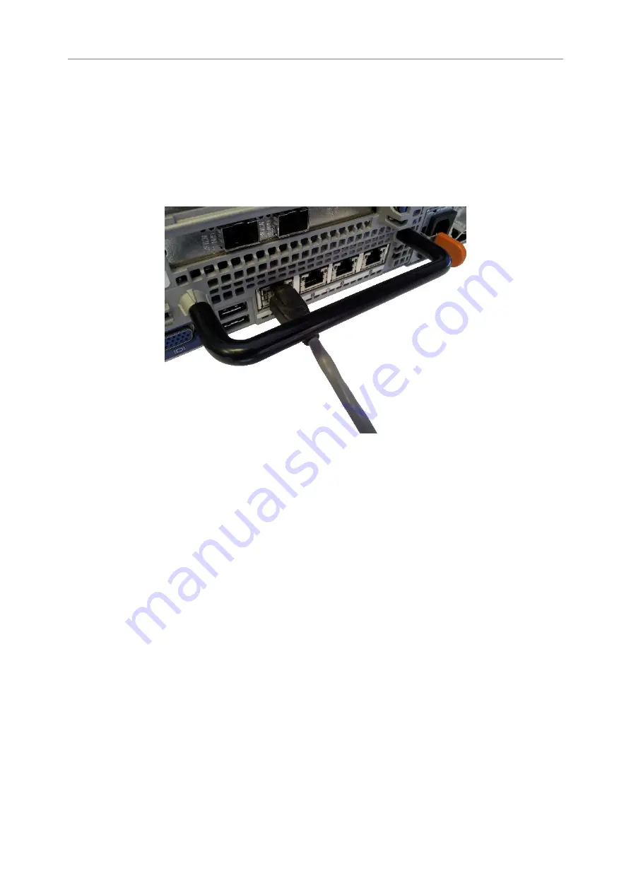
To connect an onboard interface, insert a Cat 5e cable (or better) into it as shown in the following

image. When the plug is in the correct position a “click” should be heard. The other end of the
cable should be connected to a network.

Rear Panel of the Appliance Showing Ethernet Cable Connections

Connecting the 10Gb Ethernet Cables

Depending on the configuration you have purchased, either one of the following cables will be
required for your product.

• LC Multi-mode Optical Fibre Cable (SFP+)

• Copper Interface Cable (SFP+)

• 10GBASE-T Category 6 or 6a Cable (RJ45)

Using a LC Multi-mode Optical Fibre Cable (SFP+)

If you have purchased a 10GBASE-SR feature card, connections up to 300 metres are supported
using OM3 or OM4 grade Multi-mode Optical Fibre 50/125 using LC connectors.

To connect the Appliance to an Ethernet network or directly to a device, insert one or two SFPs into

the unit.

9

Summary of Contents for a204

Page 1: ...Appliance a204 Hardware Manual Eli v5 03 191 Bridgeworks Unit 1 Aero Centre Ampress Lane Ampress Park Lymington Hampshire SO41 8QF Tel 44 0 1590 615 444 Email support 4bridgeworks com ...

Page 2: ...l Fibre Cable SFP Multi mode Optical Fibre 50 125 OM3 or OM4 Patch Cable LC up to 300 meters Or Copper Interface Cable SFP SFP Direct Attach Copper DAC Twin Ax interface cable passive up to 7 meters Bridgeworks Part Number 017 034 Or 10GBASE T Category 6 6a Cable RJ45 Category 6 certified cable with an RJ45 style connector up to 55 meters Category 6a certified cable with an RJ45 style connector up...

Page 3: ...equire at least one Multi mode Optical Fibre 50 125 OM3 OM4 Patch Cable LC of suitable length to go between your Appliance and device host or Fibre Channel switch If you are in any doubt please contact your reseller for assistance 3 ...

Page 4: ...t Cables 9 2 3 1 Using a LC Multi mode Optical Fibre Cable SFP 9 2 3 2 Using a Copper Interface Cable SFP 11 2 3 3 Using a 10GBASE T Category 6 or 6a Cable RJ45 11 2 4 Connecting the 6Gb SAS cables 11 2 5 Connecting the 12Gb SAS cables 12 2 6 Connecting the Fibre Channel Interface 13 2 7 Connecting the Power Supply 14 Appendix A Visual Indicators 16 A 1 Ethernet 16 Appendix B Technical Specificati...

Page 5: ...uickly identify different pieces of information This icon represents a note of interest about a step or section of information This icon represents an important piece of information This icon represents a warning Care must be taken and the warning should be read thoroughly 5 ...

Page 6: ...rised service center to perform any servicing inside the Appliance the user should not attempt to service any parts inside the unit themselves The power cord is used as a disconnection device be aware after disconnection of the AC power some internal components may retain charge still and represent a shock hazard Do not use the equipment where it can get wet Protect equipment from liquid intrusion...

Page 7: ...ct Certain models will use a Small Form factor Pluggable SFP Transceiver module for connection to an optical network These devices may use a Class 1 Laser device it is important that you do not stare into the Laser beam 7 ...

Page 8: ...mage is a representation of the back of the Appliance and can be used to identify the positions of the various feature cards available on your product Product Onboard Ports MA and MB Onboard Ports 9A and 9B WANrockIT 400 Management WAN WANrockIT 800 Management WAN PORTrockIT 400 Management WAN PORTrockIT 800 Management WAN All other slots will contain feature cards chosen at time of purchase Conne...

Page 9: ...other end of the cable should be connected to a network Rear Panel of the Appliance Showing Ethernet Cable Connections Connecting the 10Gb Ethernet Cables Depending on the configuration you have purchased either one of the following cables will be required for your product LC Multi mode Optical Fibre Cable SFP Copper Interface Cable SFP 10GBASE T Category 6 or 6a Cable RJ45 Using a LC Multi mode O...

Page 10: ...ome pre installed when a 10GBASE SR feature card has been purchased with your configuration Insert the multi mode cables in to the SFP as shown below When the plug is in the correct position a click should be heard 10 ...

Page 11: ...and 100 meters for Category 6a To connect the Appliance to an Ethernet network or directly to a device connect one side of the Category 6 Ethernet cable into a RJ45 port located on a 10 Gigabit Ethernet card at the back of the unit When the plug is in the correct position a click should be heard Connect the other side of the cable to your Ethernet network or device Connecting the 6Gb SAS cables Th...

Page 12: ...at speeds of up to 12Gbits s However devices that operate at slower speeds 3 Gbits s and 6Gbits s can still be connected to this SAS bus The Appliance will automatically negotiate with these devices to obtain their optimal operating speed upon power up Each SAS wide port can support up to 4 phys Connect the SAS cable s to the Appliance as shown below ensuring that connector is the correct way up 1...

Page 13: ...hich link speed you are using as the Appliance will automatically negotiate the best speed when first powered up To connect to the Fibre Channel network a Small Form factor Pluggable SFP interface module must be inserted into the SFP receptacle at the back of the Appliance as shown in the following image Note Only use SFP transceivers that meet or exceed the following standards EU IEC EN 60825 1 N...

Page 14: ... be heard Connecting the Power Supply Important Before connecting the power cord ensure that the wall or rack plug is removed or is switched off With a redundant power supply configuration the system evenly distributes power across both power supplies to maximise efficiency In order to utilise this feature please ensure that both power supplies are connected Connect the power supply to the rear of...

Page 15: ...To turn on the Appliance push the switch on the front as shown below Whenever the Appliance is powered on the switch will be illuminated in the colour green and system fans will be easily heard 15 ...

Page 16: ...Ethernet 1 Link indicator 2 Activity indicator Link Activity Description Off Off Not connected Amber Connected at less than maximum speed Green Connected at maximum speed Flashing Green Data is being sent or received 16 ...

Page 17: ...5A Maximum power consumption 750W 1100W approx Environmental Operational temperature 10 C to 35 C Non operational temperature 40 C to 65 C Humidity 10 80 non condensing Onboard Management Interface No of interfaces 2 Physical RJ45 8P8C Speed Auto sensing 10 100 1000Mb s Standards IPv4 NTP SNMP DHCP Onboard WAN Interface No of interfaces 2 Physical RJ45 8P8C Speed Auto sensing 10 100 1000Mb s Featu...

Page 18: ...Mb s Error Recovery ERL0 ERL1 ERL2 Standards IPv4 iSCSI iSNS CHAP DHCP Fibre Channel 8Gb Feature Card No of interfaces 2 Physical SFP mini GBIC Speed Auto sensing 2 4 8Gb s Standards FC AL FC PLDA FC TAPE FC PH FC FLA FCP SCSI FC FS Topology NL_port FL_port N_port F_port SAS 6Gb Feature Card No of wide ports 2 Physical SFF 8088 External Mini SAS Phys per wide port 4 Speed Auto sensing 1 5 3 6Gb s ...

Reviews: