background image

www.BrickElectric.com 

Web access URL:   

http://192.168.1.105/setpara[61]=1 

Socket command text: 

setpara[61]=1; 


4.3 DHCP Function 

BEM11000 supports both DHCP and static IP Addressing. For communication reliability, 

we recommend using a Static IP Address when you feel comfortable doing so.  This will 

ensure that the device will always be where you expect it to be, when you try to connect to 

it. 


DHCP  stands  for  Dynamic  Host  Configuration  Protocol  and  basically  means  that  your 

router will assign the first available IP Address in the list of IP Addresses Range to your 

device. This technology makes network devices very easy to use, but it is not as reliable 

because in certain circumstances it will cause the IP Address it assigns to change. DHCP 

mode is recommended when you only use Internet control, or your local software is able 

to detect module IP changes. 


Assuming module current IP Address is 192.168.1.105 for all the following commands. 


Enable/Disable DHCP 

Note: modification only effective after parameter saving and module reboot. 

To Enable DHCP: 

Web access URL:   

http://192.168.1.105/setpara[0]=1 

Socket command text: 

setpara[0]=1; 


To Disable DHCP and use static IP: 

Web access URL:   

http://192.168.1.105/setpara[0]=0 

Socket command text: 

setpara[0]=0; 


4.4 Static IP Address 

This technology is the antithesis of DHCP in that it is manually set IP address and does 

not dynamically change without direct action. The disadvantage of this method is that, if 

done  incorrectly,  can  make  the  module  unreachable  through  any  standard  means.  This 

usually happens when an IP Address is statically set to an IP Address outside of the range 

of the router, or another device on the network obtains this IP address via DHCP. If this 

happens, see the 

section of this guide titled “Reset Function”. This method is the preferred 

and more reliable way to  handle network IP Address allocation. For improved  reliability, 

the IP Address assigned to this Module should be reserved on your router. 


Summary of Contents for BEM11000

Page 1: ...M11000 is POE Supply Input Ethernet Remote I O Module with 2 output Relays channels remote control module Its Ethernet connector provides 10 100baseT interface It supports EasyBus simple solution HTTP...

Page 2: ...cations 7 4 2 Save Parameters 7 4 3 Reboot 7 4 3 DHCP Function 8 4 4 Static IP Address 8 4 5 Relay outputs control 9 4 7 Http port setting 11 4 8 Hardware reset button 12 4 9 Identification customized...

Page 3: ...to 85 Module Size 91mm x 53mm x 18mm Weight 1 2 Connection Diagram Fig 1 1 2 Specifications 2 1 Recommended Operating Conditions Parameters At T 25 unless otherwise specified Symbol Values Unit Min Ty...

Page 4: ...ault Settings IP Setting IP address 192 168 1 105 Subnet Mask 255 255 255 0 Gateway 192 168 1 1 DHCP disable Latest Firmware Version V100 0 02 You can download latest firmware for free HTTP function S...

Page 5: ...e is to make it work by minimum steps For more information please refer to later chapters 3 1 HTTP Mode 1 Connect BEM11000 with your routers or computer via a standard Ethernet POE cable see fig 1 1 a...

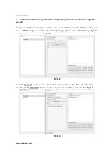
Page 6: ...tool if you don t have any or you don t know what a TCP test tool is you can use BE Manager it is within our software package Open it and see the following Fig 1 2 Fig 1 2 3 Click Connect button and w...

Page 7: ...the module at the simple start manual delivered together with module package You can also change the MAC address to use your own MAC address 4 2 Save Parameters After power cycle BEM11000 will lose i...

Page 8: ...t IP Address is 192 168 1 105 for all the following commands Enable Disable DHCP Note modification only effective after parameter saving and module reboot To Enable DHCP Web access URL http 192 168 1...

Page 9: ...168 1 105 setpara 4 100 Socket command text setpara 1 192 setpara 2 168 setpara 3 2 setpara 4 100 Set static Gateway Address Note modification only effective after parameter saving and module reboot T...

Page 10: ...ara 46 Normal ON OFF TOGGLE Normal on off toggle operation changes the relay output status immediately after receiving commands No timing features included Switches To switch off ch1 output Web access...

Page 11: ...45 1 Socket command text getpara 45 1 4 7 Http port setting In default conditions HTTP port is always 80 if you enter directly in web browser a URL without any additional parameters But in some applic...

Page 12: ...green and red LEDs are both on then continue to press the button for 10 seconds Module will erase its firmware and try to download latest firmware from Internet Please connect to internet when you do...

Page 13: ...s both TCP Server and TCP Client mode both mode has its application advantage Additionally one configurable communication watchdog can be setup to monitor the connection between Ethernet relay module...

Page 14: ...for example to 5000 Web access URL http 192 168 1 105 setpara 131 5000 Socket command text setpara 131 5000 EasyBus Client Mode For applications it is better to listen at the server and let the relay...

Page 15: ...ss URL http 192 168 1 105 setpara 130 5000 Socket command text setpara 130 5000 EasyBus Client DNS Enable For some applications the remote server IP address is assigned by DHCP so to get the actual ad...

Page 16: ...rtain moment the TCP connection will be lost You can actively access http interface to reboot the relay module so it will try to connect to server again but you can also use the additional watchdog pr...

Page 17: ...to ping mode select default is fixed IP mode 2 Configure Fixed IP or Domain Name default is your gateway IP 3 Configure programmable reboot sequence default is no action 4 Set time between pings defau...

Page 18: ...nnel 1 Web access URL Write http 192 168 1 105 setpara 101 192 setpara 102 168 setpara 103 1 setpara 104 100 Read http 192 168 1 105 getpara 101 192 getpara 102 168 getpara 103 1 getpara 104 100 Socke...

Page 19: ...ase of remote IP device becomes unresponsive auto ping function will run a pre set reboot sequence to make a customized reboot action according to your application For this function the following comm...

Page 20: ...65535 seconds Normally 60 seconds should be useful for most applications To setup time you need to set 2 parameters time unit and time Auto Ping Channel 1 1 To set time unit to millisecond setpara 45...

Page 21: ...xt Write setpara 158 5 Read getpara 158 1 6 Delay time after reboot After auto ping detected an external controller unresponsive failure and running a reboot sequence it is naturally necessary that th...

Page 22: ...ping function please make sure your every other setting is finished so it can work correctly If you save settings after auto ping start when power on the device auto ping will automatically start aga...

Page 23: ...multiple output module When one input is mapped to one or more outputs then if this input is triggered all the outputs that it mapped will also be triggered immediately 6 1 X Connect Map Setting Each...

Page 24: ...3 VWSL3 X Connect CH3 input select 1 8 105 4 VWSL4 X Connect CH4 input select 1 8 106 5 VWSL5 X Connect CH5 input select 1 8 107 6 VWSL6 X Connect CH6 input select 1 8 108 7 VWSL7 X Connect CH7 input...

Page 25: ...CH7 target IP 4 0 255 161 8 VWSIP81 X Connect CH8 target IP 1 0 255 162 8 VWSIP82 X Connect CH8 target IP 2 0 255 163 8 VWSIP83 X Connect CH8 target IP 3 0 255 164 8 VWSIP84 X Connect CH8 target IP 4...

Page 26: ...5 Relay 2 output control Write Read To look into Modbus TCP frame structure or create your own Modbus TCP program here are the detailed message frame for each command To switch on relay channel 1 outp...

Page 27: ...lic 192 168 1 105 1 3 6 SNMP get command read a SNMP entry for example to read relay channel 1 snmpget v 1 c public 192 168 1 105 1 3 6 1 4 1 55333 1 1 45 SNMP get command read a SNMP entry for exampl...

Page 28: ...earning the old fashioned and very detailed industry automation communication protocol before they can really start to do anything How to send a correct switch command Example set parameter 45 to valu...

Page 29: ...mask 4 default value 0 range 0 255 013 MAC1 MAC address 1 default value XX unique by every device range 0 255 014 MAC2 MAC address 2 default value XX unique by every device range 0 255 015 MAC3 MAC a...

Page 30: ...max 48 chars 026 TIMEOP total operation time in seconds default value range 027 TSYSON operation time in seconds after power on reset to 0 after each reboot default value range 028 SAVE save parameter...

Page 31: ...041 reserved parameter default value range 042 reserved parameter default value range 043 reserved parameter default value range 044 reserved parameter default value range 045 IOVAL01 I O value channe...

Page 32: ...value channel 10 0 off 1 on default value range 055 IOVAL11 I O value channel 11 0 off 1 on default value range 056 IOVAL12 I O value channel 12 0 off 1 on default value range 057 IOVAL13 I O value c...

Page 33: ...brickelectric com Skype Online Support 86 182 1730 3961 WhatsApp Online Support 86 182 1730 3961 Call Us 86 182 1730 3961 If you have any questions or any customized software hardware requirement plea...

Reviews: