- 28 -
mekfarmer
K 270
macchine agricole
4.5 ROLLER HYDRAULIC SYSTEM
CAUTION
After having carried out the preliminary operations in the correct way, i.e. hitched to the three points of the tractor and en-
gaged the driveline, the pipes of the hydraulic circuit mustbe connected to the relative hydraulic taps on the tractor in order
to allow the various components of the implement to operate.
The hydraulic pipes have identification labels that depict:
A. Rear roller lowering
B. Rear roller lifting
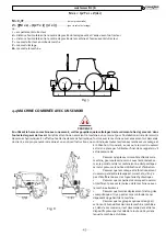
The two cylinders (
1
Fig.
10
), have an automatic release valve (
2
Fig.
10
).
Fig.10
KEY to Fig. 10
(Hydraulic layout showing roller adjustmentwith two hydraulic cylinders)
MAXIMUM PRESSURE 180 Bar
ALL PIPES ARE THE 1/4” SIZE
1. Roller control cylinders
2.
3/8” gas locking valve
3. Flow divider valve
4. Sheath to protect the hydraulic pipes
A. Roller lowering control oil pipe
B. Roller lifting control oil pipe
4.5.1 SEEDER COUPLING HYDRAULIC SYSTEM
2
1
1
3
4
Fig. 11
CAUTION
Said system relates to hydraulic seeder coupling (if fitted to the machine) After correctly fitting the coupling on the machine,
to check correct lifting operation, connect the coupling hydraulic pipe to the tractor pickup and pressurise so as to permit
Summary of Contents for mekfarmer K 270
Page 84: ... 84 mekfarmer K 270 macchine agricole ...
Page 87: ...mekfarmer K 270 macchine agricole 87 Tav 2 ...
Page 92: ...mekfarmer K 270 macchine agricole 92 Tav 7 ...
Page 93: ...mekfarmer K 270 macchine agricole 93 Tav 8 ...
Page 94: ...mekfarmer K 270 macchine agricole 94 Tav 9 E1100303 E0500103 8064512 3177557 ...
Page 95: ...mekfarmer K 270 macchine agricole 95 Tav 10 ...
Page 96: ...mekfarmer K 270 macchine agricole 96 Tav 11 ...
Page 100: ...mekfarmer K 270 macchine agricole 100 Tav 15 ...
Page 102: ...mekfarmer K 270 macchine agricole 102 ...
Page 103: ......

