background image

TBQ/TBS EVAPORATIVE COOLER INSTALLATION MANUAL  

|  

19


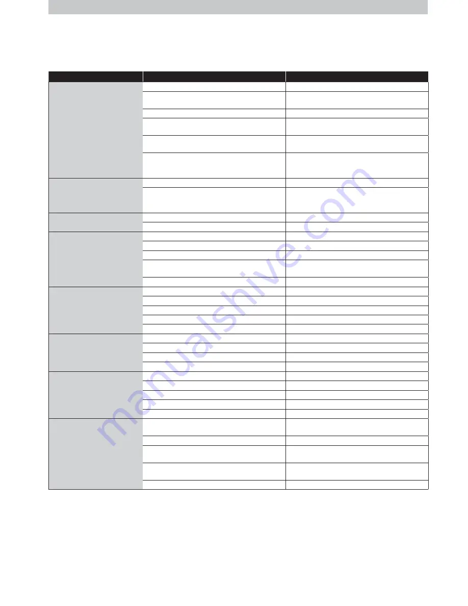
TROUBLE SHOOTING

Symptom

Cause

Action

Inadequate cooling

Under-sized cooler.

Replace with larger cooler.

Under-sized ducts.

Carry out cooling load design to determine correct size unit, 
ducting and outlets required.

Clogged or dirty cooling pads.

Clean or replace pads.

Dry pads or lack of water while cooler is operating.

Check water distribution system for possible obstruction in 
hoses.  Check pump.

Insufficient air discharge openings or inadequate exhaust 

from building, causing high humidity and discomfort.

Make sure there is adequate provision for exhausting stale 

air from building (open windows and doors).

Excessive ambient humidity (see also item above re 
inadequate exhaust).

On days during summer when ambient humidity is high the 
cooler will not reduce the temperature as much as on drier 
days.  There is no remedy except to shut off the pump.

Noisy cooler

Fan out of balance due to dirt, etc.

Clean the fan.

Too much back pressure. 
Tight duct bends. 
Grilles too small.

Re-evaluate design; improve duct layout; change grille sizes.

Pump fails to operate.

Circuit breaker tripped.

Check pump for faults. Replace if necessary.

Pump motor failure.

Replace pump.

Fan fails to start.

Main power circuit breaker tripped.

Check cause of overload.  Reset circuit breaker.

Fan motor burned out.

Replace motor.

Low system voltage.

Consult with power supply authority.

Check fault condition via the tri-colour LED on cooler 

electronics module.

Rectify fault as indicated and restart the cooler.

MagIQtouch Controller failure.

Replace MagIQtouch Controller.

Pump runs but no water circulation  
or Pump runs but pads lack water

Insufficient water in tank.

Adjust float level.

Water hoses blocked.

Check and clean out blockage.

Pump strainer blocked.

Clean pump strainer.

Insufficient water supply pressure

Check and confirm water supply pressure

Water solenoid is installed incorrectly

Check installed in the correct water flow direction

Continuous overflow of water.

Float valve adjustment not correct.

Adjust float valve.

Heavy pad deposits.

Clean or replace pads.

Drain Valve failure.

Replace Drain Valve.

Water solenoid is installed incorrectly

Check installed in the correct water flow direction

Water entering cooler outlet.

Loose water hose connections.

Tighten connections.

Water hose broken.

Replace cracked or broken hoses.

Cover not fitted on float valve.

Replace float valve.

Pads not fitted correctly into pad frames.

Install pad frame correctly.

Incorrect or damaged pads.

Replace with new Chillcel pads.

Unpleasant odour.

New cooler pads.

Drain tank, refill, run pump for a few hours. Odour will 

dissipate after a number of hours of operation.

Cooler located near source of unpleasant odour.

Remove source of odour or relocate cooler.

Algae in tank water.

Drain pan, clean thoroughly with strong cleansing agent, 

refill, change pads.

Pads remain wet after shut down.

Run fan on "vent" for 10 minutes after cooling cycle to dry 
pads out.

Heavy pad deposits.

Clean or replace pads.

Summary of Contents for TBQ

Page 1: ...INSTALLATION MANUAL TBQ TBS Evaporative Cooler Original English Instructions ...

Page 2: ...THE FLOAT VALVE 12 MAINS WATER CONNECTION 12 INSTALLING THE VENTURI FAN ASSEMBLY 13 ELECTRICAL CONNECTION 13 CONNECTING THE WATER PUMP 14 CONNECTING THE MAGIQTOUCH CONTROLLER 15 MAGIQTOUCH CONTROLLER DISPLAY INFORMATION 15 SETTING THE WATER LEVEL 15 SETUP FOR BLEED FUNNEL 15 FAULT CODES INDICATED BY LED s ON THE ELECTRONICS MODULE 16 COMMISSIONING THE COOLER 16 COMMISSIONING COMPLETION CHECKLIST 1...

Page 3: ...ss it just is a matter of looking at the job to be done and considering what action s are necessary so the person doing the job does not injure themselves SAFETY cont This should be considered in terms of What are the chances of an incident happening What could the possible consequence be What can you do to reduce or better still completely eliminate the risk Some points to consider What is the be...

Page 4: ...Guide Step 21 FINAL CHECK Complete the commissioning checklist at the end of this document Step 2 COOLER LOCATION Check cooler location Consider regulations Discuss with customer Step 8 CHECK WEATHER DAMPER Check operation of the weatherdamper Ensure weatherdamper moves freely Step 13 INSTALL DRAIN VALVE Where provided Never drain waste water directly onto the roof Be sure to use supplied O Rings ...

Page 5: ...duit and terminate in the junction box Step 16 INSTALL VENTURI FAN Ensure the venturi is fully located into the tank and the motor lead is not caught or pinched Step 6 MOUNT DROPPER Position level and secure the dropper Flash the dropper to prevent water ingress into the roof cavity Step 12 LOCAL REGULATIONS Read and adhere to local electrical and plumbing rules and regulations Step 17 ELECTRICAL ...

Page 6: ... not between the antenna and the transmission tower that is providing the television signal to the home Allow adequate access to and around the cooler for maintenance Provision must be made for access to electricity water supplies and drains Note Do you need to discuss the installation of items like safety anchor points with the customer ILL1150 A ILL1155 C ILL1155 C Lift the venturi and fan assem...

Page 7: ...eeds 43m s 141fps In exposed or very high wind areas use 16 screws minimum shank diameter 5 2mm 7 32 to secure the dropper In areas subject to windstorms hurricanes or where the cooler is located more than 8m 26 above the ground seek advice from a structural engineer The dropper may now be flashed to the roof Make sure there is no chance of water entering the roof space SECURING THE DROPPER TRANSI...

Page 8: ...ecured objects are removed beforehand WEATHER DAMPER Break off both clips on the transition that retain the weatherdamper Ensure that the weatherdamper flaps open all the way and do not interfere with the dropper or any screws The flaps should move freely through 90º Important There must be no obstructions to the weatherdamper opening fully as it will adversely affect the performance of the cooler...

Page 9: ...e and control cable Pass the taped end of the wall control cable through the conduit adaptor factory fitted in the transition and leave about 0 5m 20 in the water tank Take the power cable and drop the non plug end down the hole where the electronics module was and pass it through the conduit adaptor Important Pass the wall control cable through the conduit first Lock the power cable socket in pla...

Page 10: ...re that the water pipe connection does not place sideways strain onto the float valve Important In areas subject to freezing the water supply line to the cooler requires a drain down facility at the lowest point in the water supply pipe Important Flush the water pipe to remove any swarf before final fitting Swarf can lodge in the solenoid and float valve preventing them from functioning correctly ...

Page 11: ...NT You have the choice of installing a water management system including a drain valve water sensor and inlet solenoid or a bleed funnel Both systems provide overflow and water drain features however the water management system is also designed to actively reduce salt and mineral deposits in the air cooler INSTALLING THE BLEED FUNNEL ALTERNATIVE The bleed funnel is a simplified alternative to the ...

Page 12: ...ed funnel option a 3 4 to 1 2 BSP adaptor is to be fitted with the washer to the extension tube as shown Connect the main water supply to the water inlet point under the air cooler using the 1 2 BSP Nut and olive fitting or 1 2 BSP 1 4 brass compression adaptor fitting as required Always install a shut off valve do not use a non return type valve close by the air cooler ILL972 C ILL985 E INSTALLIN...

Page 13: ...ank Failure to do this may result in the cable being caught between the outside of the bracket and the venturi B NOTE Ensure the steel restraint cable and motor cable are secured against the side of the venturi by the sticker ELECTRICAL CONNECTION Connect the motor cable to the base of the electronics module It is a polarised plug and will only insert one way Ensure it is secured fully so that its...

Page 14: ...NING Do not run the pump while the pad frames are off and the fan is on Once plugs are connected switch the electronics module on Important Ensure the flexible splash protection cover is in place ILL1061 C ILL1095 B LEGEND A Control Cable B Speed Adjustment C Inlet Solenoid D Water Sensor or Shorting Plug E Drain Valve F Pump G Operation Fault code LED s Ensure the cables cannot rest in the water ...

Page 15: ... disconnect the pump making sure the plug is kept away from any water Turn the power back on ILL1663 A Once the water level is correct isolate the control box and connect the pump plug CONNECTING THE MAGIQTOUCH CONTROLLER Refer to the installation manual provided with the MagIQtouch Controller for instructions on installing the controller The wall control cable plugs into the electronics module A ...

Page 16: ...ronic module upside down or misaligned Water too pure for the probes to sense water is present Pressure build up in pipes can lock up the solenoid valve when a non return isolation valve is used in the water supply line It is recommended to use a ball valve i e NOT a non return type of shut off valve Check drain valve is closing and not cycling due to debris being caught under drain valve washer F...

Page 17: ...egulations and is wired back to the distribution board on its own separate circuit CHECK CABLES Cables have been correctly connected to the control boxes Power supply Motor cable Control cable Drain valve Solenoid cable Pump cable Probe cable where fitted OWNER INSTRUCTIONS The owner has been instructed how they can electrically isolate the unit at the meter box in case of an emergency DUCTWORK NO...

Page 18: ...nity Measurement replaces water when Salinity level reaches set point Timed Drain drains Tank After 8 tank fill cycles or every 1 2 hours system dependant No Drain Control salinity control external to electronics eg continuous bleed No Water Thermostatic allows Thermostatic control in VENT mode No water present Cooling performance is limited WEATHER SEAL OPEN SPEED The cooler fan will turn on at t...

Page 19: ...y Check fault condition via the tri colour LED on cooler electronics module Rectify fault as indicated and restart the cooler MagIQtouch Controller failure Replace MagIQtouch Controller Pump runs but no water circulation or Pump runs but pads lack water Insufficient water in tank Adjust float level Water hoses blocked Check and clean out blockage Pump strainer blocked Clean pump strainer Insuffici...

Page 20: ...model selected AU 1502 864655 A MANUFACTURED BY SEELEY INTERNATIONAL PTY LTD 112 O SULLIVAN BEACH RD LONSDALE SA 5160 AUSTRALIA IMPORTED BY SEELEY INTERNATIONAL EUROPE LTD 5 PAPPLEWICK LANE HUCKNALL NOTTINGHAM NOTTINGHAMSHIRE NG15 7TN UNITED KINGDOM SEELEY INTERNATIONAL AMERICAS LTD 1202 NORTH 54TH AVENUE BUILDING 2 SUITE 117 PHOENIX ARIZONA 85043 USA Service All regions Please contact your local ...

Reviews: