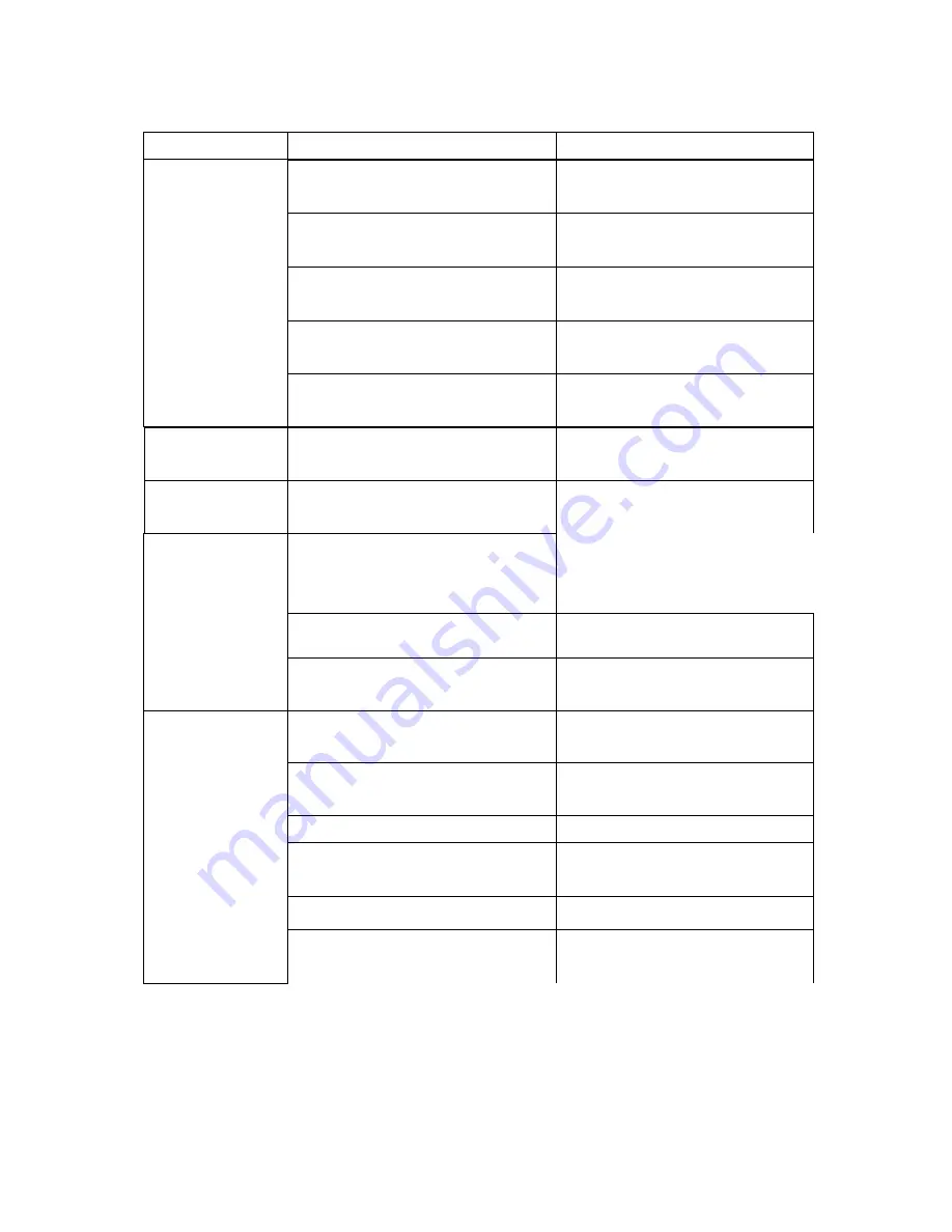
Brecknell LP250 User Manual Download Page 41


5.2 Print Problem 

Problem

Possible Cause

Recovery Procedure

Not Printing 

Check if interface cable is well 

connected to the interface connector. 


The serial port cable pin configuration is 

not pin to pin connected. 

Please replace the cable with pin to pin 

connected. 

The serial port setting is not consistent 

between host and printer. 


The port specified in the Windows driver 

is not correct. 

Select the correct printer port in the 

driver. 

The Ethernet IP, subnet mask, gateway 

is not configured properly. 

Configure the IP, subnet mask and 

gateway. 

No print on the label


Follow the instructions in loading the 

media. 

Continuous feeding 

labels 


Please do the initialization and 

gap/black mark calibration. 

Paper Jam 

Gap/black mark sensor sensitivity is not 
set properly (sensor sensitivity is not 
enough) 

Calibrate the gap/black mark sensor.

Poor Print Quality 

35

Re-connect cable to interface. 

Please reset the serial port setting.

Label loaded not correctly.

The printer setting may go wrong.

Make sure label size is set properly.

Remove the stuck label. 

Top cover is not closed properly.

Clean the print head. 

Check if print density is set properly.


Set label size exactly as installed paper 
in the labeling software or program. 

Labels may be stuck inside the printer 

mechanism near the sensor area. 


Close the top cover completely and 
make sure the right side and left side 
levers are latched properly. 

Wrong power supply is connected with 

printer. 

Check if 24V DC output is supplied by 
the power supply. 

Check if supply is loaded correctly.

Reload the supply. 


Check if dust or adhesives are 

accumulated on the print head. 


Adjust the print density and print
speed.

Check print head test pattern if head 

element is damaged. 

Run printer self-test and check the print 
head test pattern if there is dot missing 
in the pattern. 


Summary of Contents for LP250

Page 1: ...LP250 LP250W DIRECT THERMAL BAR CODE PRINTER USER S MANUAL...

Page 2: ...art the Diagnostic Tool 18 3 3 2 Printer Function Calibrate sensor Ethernet setup RTC setup 19 3 4 Setting Ethernet by Diagnostic Utility Option for LP 250 model 20 3 4 1 Using USB interface to setup...

Page 3: ...the Black Mark Sensor 32 4 3 5 Set Gap Sensor as Media Sensor and Calibrate the Gap Sensor 32 4 3 6 Skip AUTO BAS 32 5 Troubleshooting 34 5 1 LED Status 34 5 2 Print Problem 35 5 3 LCD display Option...

Page 4: ...i...

Page 5: ...nadian ICES 003 T V Safety EN60950 1 IEC 60950 1 Wichtige Sicherheits Hinweise 1 Bitte lesen Sie diese Hinweis sorgf ltig durch 2 Heben Sie diese Anleitung f r den sp teren Gebrauch auf 3 Vor jedem Re...

Page 6: ...UND ANDERE K RPERTEILE FERNHALTEN VORSICHT EXPLOSIONSGEFAHR BEI ERSATZ DER BATTERIE DURCH UNZUL SSIGEN TYP VERBRAUCHTE BATTERIEN IMMER VORSCHRIFTSGEM SS ENTSORGEN Note The maximum printing ratio per...

Page 7: ...in case you need to reship the printer Unpacking the printer the following items are included in the carton One printer unit One Windows labeling software Windows driver CD disk One quick installation...

Page 8: ...croSD card specification The DOS FAT file system is supported for the SD card Folders files stored in the SD card should be in the 8 3 filename format 2 SD card spec SD card capacity Approved SD card...

Page 9: ...3...

Page 10: ...Interior View 1 9 7 2 LP 250 Model 3 8 1 Top cover 2 Media holder 3 Media guide 4 Printhead 5 Gap sensor receiver 6 Gap sensor transmitter 7 Platen roller 8 Black mark sensor 9 Media holder lock swit...

Page 11: ...5...

Page 12: ...face 4 RS 232C interface Option for TDP 225W mode 5 Fan fold paper entrance chute 6 Ethernet interface Option for TDP 225 model 7 USB host Factory option for TDP 225W model Note The interface picture...

Page 13: ...interfaces availability 7...

Page 14: ...cord into a properly grounded power outlet Note Please switch OFF printer power switch prior to plug in the power cord to printer power jack 3 2 Loading the Media 3 2 1 Loading the Media 1 Open the pr...

Page 15: ...roll width LP 250 model LP 250W model 4 Place the roll between the holders and close them onto the core 5 Place the paper printing side face up through the media guides media sensor and place the lab...

Page 16: ...0 model LP 250W model 7 Use Diagnostic Tool to set the media sensor type and calibrate the selected sensor Start the Diagnostic tool Select the Printer Configuration tab Click the Calibrate Sensor but...

Page 17: ...Loading path for roll labels LP 250 model LP 250W model 11...

Page 18: ...e And place the paper printing side face up through the media guides media sensor and place the label leading edge onto the platen roller Rear external label entrance 4 Close the top cover gently 5 Us...

Page 19: ...Calibrate 13...

Page 20: ...to load the media 2 Open the top cover and peel off panel after calibrated the sensor Peel off panel 3 Lead the media through the backing paper opening beneath the peel off roller Backing paper openi...

Page 21: ...5 Close the top cover gently 6 Press the FEED button to test Backing paper Liner Note Please calibrate the gap black mark sensor when changing media 15...

Page 22: ...2 Lead the media through the cutter paper opening Cutter paper opening 3 Close the top cover gently 4 Use Diagnostic Tool to set the media sensor type and calibrate the selected sensor Start the Diagn...

Page 23: ...Note Please calibrate the gap black mark sensor when changing media 17...

Page 24: ...nal commands to the printer Using this convenient tool you can explore the printer status and settings and troubleshoot the printer Note This utility works with printer firmware V6 00 and later versio...

Page 25: ...19 Ethernet Setup Function Description Calibrate Sensor Calibrate the sensor specified in the Printer Setup group media sensor field Setup the IP address subnet mask gateway for the on board Ethernet...

Page 26: ...ace 1 Connect the USB cable between the computer and the printer 2 Turn on the printer power 3 Start the Diagnostic Utility by double clicking on icon Note This utility works with printer firmware V6...

Page 27: ...P address subnet mask and gateway for the on board Ethernet 5 Click the Discover Device button to explore the printers that exist on the network 6 Select the printer in the left side of listed printer...

Page 28: ...t interface setup and go back to Diagnostic Tool main screen Factory Default button This function will reset the IP subnet mask gateway parameters obtained by DHCP and reset the printer name Web setup...

Page 29: ...ard specification The DOS FAT file system is supported for the SD card 23 SD card spec SD card capacity Approved SD card manufacturer V1 0 V1 1 MicroSD 128 MB Transcend Panasonic V1 0 V1 1 MicroSD 256...

Page 30: ...Folders files stored in the SD card should be in the 8 3 filename format 24...

Page 31: ...3 6 Mount the Printer on the Wall There are three holes in the bottom of printer Printer can be mounted on the wall by the 3 0mm 3 5mm screw head screws Note Please hang properly to avoid fall down 25...

Page 32: ...LASH or CARD that you previously saved file in and press Enter key of the keyboard to list files 6 Select the file and press Enter key to run the BAS program FLASH List TEST1 BAS TEST2 BAS 7 Then you...

Page 33: ...s head open paper empty paper jam or memory error etc 4 2 Regular Button Function 1 Feed labels When the printer is ready press the button to feed one label to the beginning of next label 2 Pause the...

Page 34: ...mark sensor sensitivity The LED color will be changed as following order Amber red 5 amber 5 blinks solid green green 5 blinks green amber 5 blinks red amber 5 blinks Note 1 Sensor calibration can be...

Page 35: ...witch 3 Release the button when LED becomes amber and blinking Any amber will do during the 5 blinks The LED color will be changed as following order Amber red 5 amber 5 blinks solid green green 5 bli...

Page 36: ...r configurations and available memory space Dump mode Printer will enter dump mode after printing printer configuration In the dump mode all characters will be printed in 2 columns as following The le...

Page 37: ...following procedures 1 Turn off the power switch 2 Hold on the button then turn on the power switch 3 Release the button when LED turns green after 5 amber blinks Any green will do during the 5 blinks...

Page 38: ...er switch 2 Hold on the button then turn on the power switch 3 Release the button when LED turns red amber after 5 green amber blinks Any red amber will do during the 5 blinks The LED color will be ch...

Page 39: ...BAS program 1 Turn off printer power 2 Press the FEED button and then turn on power 3 Release the FEED button when LED becomes solid green The LED color will be changed as following Amber red 5 blinks...

Page 40: ...supply If it is not lit on power supply is broken Check both power connections from the power cord to the power supply and from the power supply to the printer power jack if they are connected secure...

Page 41: ...te the gap black mark sensor Poor Print Quality 35 Re connect cable to interface Please reset the serial port setting Label loaded not correctly The printer setting may go wrong Make sure label size i...

Page 42: ...he gap black mark sensor Set label size correctly printer mechanism Out of Mem The space of FLASH DRAM or MicroSD card is full Delete unused files in the FLASH DRAM or MicroSD card Take Label Peel fun...

Page 43: ...minute 3 Use a cotton swab and 100 ethanol to clean the print head surface Clean the print head when changing a new label roll Platen Roller 1 Turn the power off 2 Rotate the platen roller and wipe i...

Page 44: ...e print head and supply sensors once change a new media to keep printer performance and extend printer life The maximum printing ratio per dot line is 15 for this printer To print the full web black l...

Page 45: ...5 Add TDP 225W model Camille 2009 9 16 Add 3 4 section Camille 2009 9 18 Add 5 3 section Camille 2009 12 28 Revise 2 2 3 section Add USB host Camille 2010 3 3 Revise 1 2 section Camille Add 3 7 sectio...

Page 46: ...A Tel 507 238 4461 FAX 507 238 4195 Web site www wtxweb com Avery Weigh Tronix UK Foundry Lane Smethwick West Midlands England B66 2LP Tel 44 0 8453 66 77 88 Fax 44 0 121 224 8183 Email info awtxgloba...

Reviews: