


Page 29
Page 28
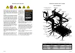
Lift Operating Instructions
Lift Power
On/Off Switch
Power
Indicator
Light
Before lift operation, park the vehicle on a level
surface, away from traffic. Place the vehicle
transmission in “Park” and engage the parking
brake. Vehicle engine must be running.
Lift Operating Instructions address operation of
the lift only.
Vehicle Doors and Vehicle Interlocks: Transit
vehicle lift doors and interlocks vary. Procedures
to operate them vary also. Lift operators
(attendants) must become familiar with the vehicle
lift access door system and vehicle interlock(s).
Manual Door(s): Open manual doors fully and
secure in full open position before operating the
lift.
Do not operate the lift if you suspect lift damage,
wear, or any abnormal condition. Refer to the
Manual Operating Instructions to manually operate
lift.
Hand-held
Pendant Control
36514
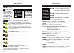
Lift Power ON/OFF Switch:
This switch must be
in the ON position in order to activate the lift. The
green Power Indicator Light illuminates to signal
power to the lift.
UP:
From ground level, the UP function will
raise (rotate) the roll stop to the vertical
position. The platform then raises to floor level
position.
DOWN: From floor level,
the DOWN function
lowers the platform to ground level and then
unfolds (lowers) the roll stop to the ramp (horizon-
tal) position.
Control Switch Functions:
Hand-held Pendant Control:
The hand-held
attendant’s pendant control is equipped with two
rocker switches. When there is power to the lift,
the lift function labels illuminate to identify the
functions.
FOLD: From floor level, the FOLD function
folds the platform inward to the stowed
position.
UNFOLD:
From stowed position, the
UNFOLD function unfolds the platform out-
ward to the floor position.
Note: If any functions do not occur as
described, discontinue lift use immediately.
D
C
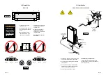
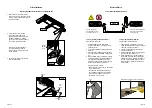
Before lift operation, park on
a level surface, away from ve-
hicular traffic. Place the vehicle
transmission in “Park” and en-
gage the parking brake. Vehicle
engine must be running. Refer
to the Manual Operating Instruc-
tions to manually operate lift.
B
A
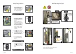
2. Press DOWN switch until
the entire platform reaches
ground level (see Photo B)
and the roll stop unfolds fully
(ramp position). See Photo C.
Release switch.
3. Unlock wheelchair brakes
and unload passenger from
platform.
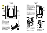
OPEN DOOR(S) AND SECURE
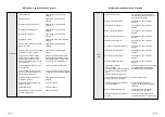
Lift Operating Instructions
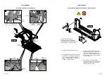
TO UNFOLD PLATFORM:
Stand clear and press the
UNFOLD switch until the
platform stops (reaches floor
level
- unfolds
fully). Release
switch.
Notice: In event platform does
not unfold, press FOLD
switch to release Lift-Tite
™
latches.
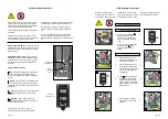
TO UNLOAD PASSENGER:
1. Read Notice below! Load
passenger onto platform and
lock wheelchair brakes.
Notice: Passenger must be
positioned fully inside yellow
boundaries, roll stop must be
UP, and roll stop latch must
be engaged.
36514


