


Page 17
Page 16
Lift Installation
Platform Angle Adjustment
Lift Installation
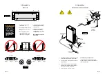
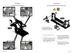
Turnbuckle Installation and Adjustment
36514
Hinged platform halves are secured with and
rotated on turnbuckles. Platform turnbuckles are
fully adjusted during assembly procedures (control
platform alignment and leveling). Turnbuckles
are disconnected from the platform brackets for
shipping purposes. Vibration during shipment can
potentially affect turnbuckle adjustment.
1. Using the hand pump, carefully deploy platform
to floor level. Be sure the platform stop blocks
are in contact with the vertical arms (Photo A).
Warning: Keep clear of platform area during
hand pump deployment. Hinged platform
halves are not secured and could free fall.
2. Manually unfold both platform halves. Keep
Hands Clear! The left platform tab must
engage the right platform slot. See Photo D.
3. Both platform halves must be laying flat as
shown in Figure 2. Install the left turnbuckle
into the platform bracket with the turnbuckle
stud facing outward (Photo B, right side
shown). Adjust turnbuckle so stud enters
the platform bracket and no tension is on the
turnbuckle (adjust if needed only). No further
adjustment of the left turnbuckle is necessary.
4. Install right turnbuckle into the platform
bracket with the turnbuckle stud facing
outward (Photo B).
5. Adjust right platform turnbuckle so that the
inboard end of the right platform is slightly
above the platform heel (Photo C).
6. Stow and deploy platform. Observe the
platform tabs and platform slots to confirm
proper alignment during platform deployment.
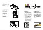
If the left platform tabs are higher than the right
platform slots, increase the length of the right
turnbuckle (Figure 1). If the tabs are lower
than the slots, decrease the length of the right
turnbuckle.
Note:
Loosen jam nut
to adjust turnbuckle
length. Tighten jam nut
after adjustment.
Shorten
Turnbuckle
Lengthen
Turnbuckle
Jam Nut
Figure 1
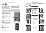
Figure B
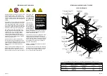
Lowering Sequence Requirements
1. The outboard end (toe) of
the platform must contact
the ground first to ensure the
spring-loaded outer barrier
unfolds fully. See Figure B.
2. The inboard end (heel) of the
platform must lower fully (turn-
buckle brackets must contact
ground when fully lowered).
See Figure B.
The angle of the platform at
ground level directly affects the
angle of the platform when posi-
tioned at floor level.
Raise the platform to floor level.
Note the angle of the platform.
The platform at floor level should
have a slight upward angle as
shown in Figure C.
Adjust platform angle as detailed
below.
Floor
Level
Wedges (option)
Figure C
(Heel) Inboard
Outboard (Toe)
Rear
Front
Outboard
(passenger's side)
Inboard
(driver's side)
“Arrows/Direction
(of vehicle)
(of vehicle)
Heel
Ground Level
Barrier must
unfold
fully.
Platform heel
must lower
fully.
Barrier
2
1
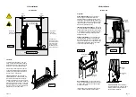
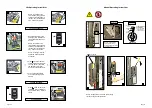
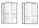
Adjustment Procedure:
Platform angle adjustment
Allen screws are provided on
each side of the platform (see
photo at right).
Turn adjustment screws clock-
wise to raise the outboard end
of the platform. Turn adjust-
ment screws counterclockwise
to lower the outboard end
of
the platform.
Both adjustment screws must
be adjusted equally.
Platform Stop Blocks:
When
adjusting platform angle, en-
sure both stop blocks are mak-
ing full contact with the vertical
arms (see photo at right).
Floor Level Adjustment:
Following platform angle
adjustment, set platform
floor level positioning as
detailed in Tower Micro-
switch Adjustmen
t.
Check
platform angle again
after performing Tower
Microswitch Adjustment
procedures.
Turnbuckles:
Platform
turnbuckles will be affected
if platform angle is ad-
justed. Adjust turnbuckles
as detailed in Turnbuckle
Adjustment section if
needed.
Stop
Block
Vertical
Arm
Adjustment Screw
Stop blocks must
make full contact.
A
36514