background image

Sa

fe

ty

 in

for

m

at

ion

9

Occupant restraints

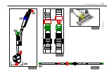
400mm

(16in)

FCZ

HHT

200mm

(8in)

200mm

(8in)

• 

Wheelchair users, their carers and family are advised to check vehicle 

specifications to ensure that sufficient floor space is available to 

accommodate the wheelchair and tie-down system. These distances 

are based upon the desire to maintain clear zones for potential head 

excursions of occupants provided with both upper and lower torso 

restraints. 

• 

Users of heavy powered wheelchairs are also advised to check vehicle 

carrying capacity. If in doubt consult the vehicle supplier for further 

details. 

• 

Any airbag, as fitted to the vehicle, shall be used only as a 

supplementary occupant restraint if designed to be used in 

combination with the WTORS. 

• 

Installers of this tie-down should take note of any vehicle airbag 

position when planning the installation. Airbags can cause serious 

injury if a wheelchair-seated occupant is seated too close to an airbag 

position. If in doubt contact the vehicle manufacturer or your National 

Automotive Regulatory Body for advice.

Figure A

Summary of Contents for UI12350

Page 1: ...TOR SHOULDER BELT OCCUPANT RESTRAINT User Manual EN Instructions for fitting and use UI12350...

Page 2: ...ve maximum performance and safe operation Keep the manual in a safe place so you can refer to it when necessary If you have any questions about your equipment please contact us Once again thank you fo...

Page 3: ...Belt Equipment storage and maintenance Warranty 4 6 8 18 19 10 12 14 16 Fit and use TOR Shoulder Belt Rail Fit and use TOR Shoulder Belt Bolted Fit and use TOR Adjustable Shoulder Belt Rail Fit and u...

Page 4: ...The development of BraunAbility kits is a continuous process Applications are added on a regular basis For more details contact BraunAbility or look on the BraunAbility website 4 Occupant restraints S...

Page 5: ...T SBB T STR T SRR T STB T SRB T SBR Safety information 5 Occupant restraints T SABB T SATR T SARR T SATB T SARB T SABR...

Page 6: ...mass of 76 3kg The test dummy was restrained by both a pelvic and upper torso restraint Use of a pelvic only belt may compromise the performance of the WTORS system and should be avoided If the insta...

Page 7: ...ds Care should be taken to prevent contamination of the webbing with polishes oils and chemicals The restraint anchorages should be installed by an experienced technician vehicle converter Anchorages...

Page 8: ...of at least 450mm 18in behind and 650mm 26in FCZ front clear zone in front of the head of the wheelchair user Fig A The shoulder belt anchorage must be roof or side wall anchored at a height level suc...

Page 9: ...ints Users of heavy powered wheelchairs are also advised to check vehicle carrying capacity If in doubt consult the vehicle supplier for further details Any airbag as fitted to the vehicle shall be us...

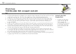
Page 10: ...drops and locks into the rail T bolts will have been fitted to 40Nm 5 Position the third point ATF fixing into the cant rail Fig 1B so that it is vertically above the inertia reel casing fixed onto th...

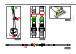
Page 11: ...DRAWING No SHEET 1 OF 1 A2 TOR SHOULDER BELT RAIL A DATE APPROVED BY DATE DIMENSIONS ARE IN MILLIMETER UNSPECIFIED TOLERANCES x xx 5 0 REMOVE ALL SHARP EDGES T SRR STOCK CODE No A B C Figure 2 CONF DO...

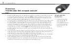
Page 12: ...e of 40Nm Note All vehicle anchorage points may require reinforcement as necessary to meet any required minimum strength recommendations for the vehicle 3 Once installed check the free running ofthe w...

Page 13: ...FINISH SPEC FINISH MATERIAL SPEC MATERIAL FOR DIMENSIONS NOT SHOWN SEE CAD DATA CAD DATA IS BASIC DRAWN BY ISSUE TITLE DRAWING No SHEET 1 OF 1 A2 TOR SHOULDER BELT BOLTED A1 DATE APPROVED BY DATE DIME...

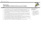
Page 14: ...tion the third point ATF fixing into the cant rail Fig 6B so that it is vertically above the inertia reel casing fixed onto the floor fixing as per point 4 6 Once installed check the free running of t...

Page 15: ...D B Figure 2 CONF DO M 3 4 5 6 7 6 7 4 5 3 SIGNATURE DATE COLOUR FINISH SPEC FINISH MATERIAL SPEC MATERIAL FOR DIMENSIO C DRAWN BY TITLE SHEET 1 OF 1 A2 TOR DIN STATIC L DATE APPROVED BY DATE DIMENSIO...

Page 16: ...y require reinforcement as necessary to meet any required minimum strength recommendations for the vehicle 3 Once installed check the free running ofthe webbing into and out of the inertia reel and ch...

Page 17: ...Fit and use 17 Occupant restraints Figure 7 A B C D E F X FINISH MATERIAL SPEC MATERIAL A B A Figure 4 90 90 C...

Page 18: ...n the vehicle is in motion All webbing and components can be cleaned as necessary but care should be taken to prevent contamination of the webbings with polishes oils and chemicals particularly batter...

Page 19: ...ucted BraunAbility have also participated in test programs with other manufacturers anchorage products and will support warranty on the BraunAbility products when used in conjunction with such jointly...

Page 20: ...ESNA WC 4 2012 Section 18 2001 85 EC R 107 06 2007 46 EC DIN 75078 2018 858 BraunAbility May 2021 Manufacturer BraunAbility UK Ltd Unwin House The Horseshoe Coat Road Martock Somerset TA12 6EY UK Phon...

Page 21: ...05 Quality system certified in accordance with ISO 9001 2008 Illustrations descriptions and specifications in the user manual are based on current product information BraunAbility UK Ltd reserves the...

Page 22: ...UI12350 BraunAbility UK Ltd Unwin House The Horseshoe Coat Road Martock Somerset TA12 6EY UK Phone 44 1935 827740 Email info braunability eu www braunability eu...

Reviews: