background image

Page 36

Stroking

Hand

Pump

 Up (To Raise):

Open

(Down)

Close

(Up/Stop)

Manual Operating Instructions

E

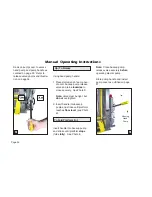
Using hand pump handle:

1. Place slotted end of pump han-

dle onto backup pump release 
valve and turn 

clockwise

 to 

close securely.  See Photo D.    

Note:

Valve must be tight, but 

do not

 overtighten.

2. Insert handle into backup 

pump and stroke until platform 
reaches

ÁRRUOHYHO

(see Photo 

E).

  To Fold Platform (In):

Insert handle into backup pump 
and stroke until platform 

stops

(folds

fully

).  See Photo E.

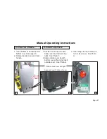
D

Remove pump cover to access 
hand pump and pump handle as 
outlined on page 33.  Refer to 
release valve photos and illustra-
tion on page 34.

Note:

  Close backup pump 

release valve securely 

before

operating electric pump.

Store pump handle and install 
pump cover as outlined on page 
37.

Summary of Contents for NVL Vista Series

Page 1: ...iate for the size and weight of the lift but must be installed on buses school buses and multi purpose passenger vehicles other than motor homes with a gross vehicle weight rating GVWR that exceeds 4...

Page 2: ...ual includes safety precautions lift operating instructions man ual operating instructions and instructions for maintenance and lubrication procedures Your lift is built for dependability and will bri...

Page 3: ...ety 15 Hand held Pendant Control 15 Lift Features Lift Tite Latches 16 17 Inner Roll Stop 18 19 Outer Barrier 19 20 Outer Barrier Operation 20 21 Bridging 21 Handrails 21 Lift Passengers Passenger Ori...

Page 4: ...k cover of this manual The warranty cards must be processed to activate the warranty Two Braun Serial No Series No LGHQWL FDWLRQ WDJV DUH SRVWHG on the lift One I D tag shown below is posted on the op...

Page 5: ...anty and Registration Instructions Model No Series No Serial No Pump Code Cylinder Code Date of Manufacture Note This information must be provided ZKHQ OLQJ D warranty claim or ordering parts Keep for...

Page 6: ...l Stop Rotating Pivot Slide Arms 2 Platform Pivot Arms 2 Pump Side Vertical Arm Bottom Parallel Arms 2 Platform Lights 2 Outboard Right Lift Terminology Illustration Lift Tite Latches 2 Unfold Assist...

Page 7: ...n procedures are identical for all NVL Series lift models The operating instructions contained in this manual and appearing on lift posted operating instructions decals address the lift control switch...

Page 8: ...d with the outer barrier Lift Tite Latches The spring loaded latches prevent the platform from unfolding from the stowed position in the event of platform drift Further details regarding Lift Tite lat...

Page 9: ...rm cannot be folded stowed if occupied The inner roll stop features a locking mechanism that prohibits the platform from lowering if the lock does not engage The lift platform cannot be raised more th...

Page 10: ...m rotating out and down from the fully stowed YHUWLFDO SRVLWLRQ WR RRU OHYHO horizontal position when the UNFOLD switch is pressed B DOWN Platform Lower Down is the action of the platform ORZHULQJ IUR...

Page 11: ...sure safe troublefree operation Safety precautions are provided to identify potentially hazardous situations and provide instruction on how to avoid them All information contained in this manual and...

Page 12: ...structions before operating the lift Note Wheelchair passengers and all transit agency personnel drivers and wheelchair lift attendants must read and become familiar with the contents of this manual a...

Page 13: ...ng func tions continuous lifting capacity is 800 lbs Discontinue lift use immediately if any lift or vehicle interlock does not operate properly Do not operate or board the lift if you or your lift op...

Page 14: ...urn powered electric wheelchairs off when on lift platform Press the DOWN switch until the entire platform rests on ground level lowered fully and the outer barrier is fully unfolded ramp position bef...

Page 15: ...worn or illegible decals Keep owner s operator s manual in lift mounted manual storage pouch at all times Never modify alter a Braun Corporation lift Do not use accessory devices not authorized by The...

Page 16: ...or securement systems are not addressed in this manual or on lift posted operating instructions decals due to the variety of proce dures required for operating them Braun Corporation NVL Series lifts...

Page 17: ...ing parts Control Switches Hand held Pendant Control The hand held attendant s pendant control is equipped with two rocker switches UNFOLD FOLD DOWN and UP The momentary switches activate the automati...

Page 18: ...ift components before attempting lift operation Refer to the Lift Terminology Illustrations IRU LGHQWL FDWLRQ RI VSHFL F OLIW Lift Tite Latches NVL Series lifts are equipped with Lift Tite Latches Lif...

Page 19: ...h is pressed press the FOLD switch mo mentarily to disengage the Lift Tite latches platform drift has occurred Then press the UNFOLD switch to unfold the SODWIRUP WR RRU OHYHO VWDQGDUG operation When...

Page 20: ...erves as a bridge plate inner roll stop photos below When the UNFOLD switch is pressed and the platform unfolds IURP VWRZ SRVLWLRQ WR RRU OHYHO this mechanical roll stop is auto matically deployed to...

Page 21: ...he inner roll stop does not operate properly Outer Barrier This spring load ed roll stop provides a ramp for wheelchair loading and unload WARNING Discontinue lift use immediately if any lift componen...

Page 22: ...inue lift operation im mediately if the outer barrier does not operate properly Note The platform must raise approximately three inches be fore the outer barrier reaches the fully vertical position se...

Page 23: ...stops the down travel attendant must view the plat form as it lowers to be certain the entire platform reaches and of the platform if the outboard end of the platform contacts a raised surface such a...

Page 24: ...ro cedures required for safe trans port of wheelchair passengers The lift operator and bystanders must keep clear of the area in which the lift operates Observe your passenger at all times during lift...

Page 25: ...nt area and clear of all moving parts Vehicle Floor Level Loading and Unloading The platform PXVW EH IXOO UDLVHG DW RRU OHYHO and the bridge plate must be prop erly positioned when loading or unloadin...

Page 26: ...any other lift com ponent does not operate as outlined in this manual discon tinue lift use immediately and contact The Braun Corporation sales representative in your area or call The Braun Corporatio...

Page 27: ...entative dealer before attempting lift operation Any questions or concerns can be answered by the sales repre sentative at that time Operate the lift through all functions with your sales representati...

Page 28: ...cy s daily lift service program Simple inspections can detect potential lift operational problems Regular preventive maintenance will reduce potential lift opera tion downtime and increase the service...

Page 29: ...to do so may result in serious bodily injury and or property damage Lift Operating Instructions Before lift operation park the ve hicle on a level surface away from YHKLFXODU WUDI F 3ODFH WKH YHKLFOH...

Page 30: ...lease switch Note In event platform does not unfold press FOLD switch to release Lift Tite latches To Unload Passenger 1 Read Note below Load passen ger onto platform and lock wheel chair brakes Note...

Page 31: ...unfolds fully ramp position See Photo C Release switch 3 Unlock wheelchair brakes and unload passenger from platform Note Outer barrier must be fully unfolded ramp position until the entire wheelchair...

Page 32: ...w Load pas senger onto platform and lock wheelchair brakes See Photo G Note Outer barrier must be fully unfolded ramp position until the entire wheelchair or standee has crossed the outer barrier See...

Page 33: ...aise the platform to RRU OHYHO See Photo J Release switch 3 Unlock wheelchair brakes and unload passenger from platform To Fold Platform Press FOLD switch until platform stops fully folded See Photos...

Page 34: ...umination when it is powered An audio warning and visual warning for public lifts will activate if the threshold area is occupied when WKH SODWIRUP LV DW OHDVW RQH LQFK EHORZ RRU OHYHO 7KH IROORZLQJ R...

Page 35: ...at differ from standard lift operation procedures The Manual Instructions decal post ed inside pump cover provides manual operating instructions also Note A right side pump lift model is depicted in t...

Page 36: ...lease valve securely before operating electric pump A normal lift operation procedures such as loading and unloading passengers Follow all Lift Op eration Safety Precautions Remove the pump cover to g...

Page 37: ...e open 1 2 turn only until the platform reaches ground level and roll stop unfolds B C Using hand pump handle Photo B 1 Close hand pump valve place slotted end of pump handle onto backup pump release...

Page 38: ...ten 2 Insert handle into backup pump and stroke until platform reaches RRU OHYHO see Photo E To Fold Platform In Insert handle into backup pump and stroke until platform stops folds fully See Photo E...

Page 39: ...lock handle To Install Pump Cover 1 Position cover over module back cover and red warning light See Photo F 2 Align outside cover lip with bottom cover offset and insert outside cover See Photo G 3 I...

Page 40: ...worn or illegible decals Part numbers are provided for decals Inspect your lift for missing worn or illegible decals Call 1 800 THE LIFT for replacements 31412 21494 30695 Note Clean surfaces as deta...

Page 41: ...d 02 Platform unfolding 03 Platform unfolding paused 04 Platform at floor level 05 Platform beginning to lower 06 Platform lowering threshold cannot be occupied from this point down 07 Outer barrier m...

Page 42: ...roperty damage WARNING 29051 MANUAL OPERATION Turn wing 1 4 turn for hand pump access 29051 Lock Unlock 1 Wide Yellow Boundary Tape 30236R order by the inch as needed WARNING Contact The Braun Corpora...

Page 43: ...ction and lubrication procedures VSHFL HG LQ WKH SUHYLRXV VHFWLRQV VKRXOG EH repeated Clean the components and the sur rounding area before applying lubricants LPS2 General Purpose Penetrating Oil is...

Page 44: ...w the lift Once stowed press the UP button on the hand pendant and the Floor Level Set but ton on the back side of the pump cover until the Lift Ready green LED stops blinking Discontinue lift use imm...

Page 45: ...Slide Arm Pivot Pins LO Lubrication Diagram Lift Tite Latch Roller Assemblies 2 LO Outer Barrier Pivot Arm Pivot Points 2 LO Outer Barrier Activation Foot Pivot Point 2 LO Outboard Platform Pivot Pin...

Page 46: ...ed or misaligned posi tive securement external snap rings and proper operation Inspect outer barrier for proper operation Apply Light Oil See Lubrication Diagram Apply Light Grease See Lubrication Dia...

Page 47: ...arrier pivot arm pivot points 2 Upper and lower fold arm telescoping area Platform pivot pin bearings 2 Platform fold axles 2 Inner roll stop lever bearings 2 Inner roll stop lever slot 2 Remove forei...

Page 48: ...or sion spring Inspect inner roll stop for Wear or damage Proper operation Roll stop should just rest on top surface of the threshold base plate Positive securement both ends Inspect handrail componen...

Page 49: ...r or damage and positive securement Inspect platform fold link rollers and bearings for wear or damage and positive securement Remove pump module cover and inspect GUDXOLF KRVHV WWLQJV DQG FRQQHFWLRQV...

Page 50: ...pivot pin 2 Hydraulic Fluid Pump Check level Note Fluid should be changed if there is visible contamination QVSHFW WKH K GUDXOLF V VWHP F OLQGHU KRVHV W WLQJV VHDOV HWF IRU OHDNV LI XLG OHYHO LV ORZ...

Page 51: ...ngs Inspect vertical arm plastic covers Inspect power cable Mounting Decals and Antiskid Tighten replace or correct as needed Apply Door Ease or replace if needed See Lubri cation Diagram Resecure or...

Page 52: ...Providing Access to the World Over 300 Braun Dealers Worldwide...

Page 53: ...n card is completed and received by The Braun Corporation within twenty days of purchase If no warranty card is received the warranty will expire three years from the date of manufacture as identified...

Reviews: