background image


OPERATING INSTRUCTIONS_____________________________________________________________ 


1) 

Turn the power switch to the ON position. 

2) 

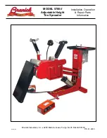
Lower the inspection platform completely using the hand control valve at the tool tray. 

3) 

Pull the bead hooks up and away from the center of the machine. 

4) 

Roll a tire up the ramp and center it on the rollers. Lower the bead hooks inside the tire making sure the bead rollers 
are inside the tire bead. The vertical position of the bead hooks is adjustable using the quick pin release on the side 
of the bead hook arm. 

5) 

Steady the tire while raising the inspection platform to a comfortable working height.


6) 

Use the tire spread hand control valve at the tool tray to spread the tire as required. The light can be positioned to 
view any portion of the tire. 

NOTE

: If the tire is lifted off the rollers when spread, release spread and move spread hooks to a lower position. 

7) 

Rotate the tire using the foot controls. Release the foot pedal to stop rotation for inspection. Rotation speed can be 
adjusted using the Speed Control dial. Repeat this operation until inspection is complete. 

8) 

When inspection is complete, close the bead hooks fully and swing them up and out of the tire.  Move the light fixture 
out of the tire. 

9) 

Lower the inspection platform completely and roll the tire off the rollers and down the ramp.


10) 

Turn the power switch to the OFF position.


ADDITIONAL FEATURES__________________________________________________________________ 


1) 

There are 4 air tool ports located below the tool tray. Attach a 

1/4” NPT quick coupler to each port and attach air tools 

as needed. 

2) 

There are two electrical outlets located on the control column. The power switch must be in the ON position to supply 
power to these outlets. 


MAINTENANCE_________________________________________________________________________ 


          MONTHLY 

–  

Inspect unit for air leaks and wear or damage on pins and rollers. 


Lubricate all moving parts (bolts, hinges, rollers, etc.) with a lubricating oil. 


YEARLY

     - Grease all bearings using grease zerks. 

CAUTION


Before servicing machine disconnect air line from the unit and unplug 

the power cord.


Summary of Contents for 5700E

Page 1: ...REV031318 P N 81 0289 MODEL 5700E Adjustable Height Tire Spreader Installation Operation Repair Parts Information Branick Industries Inc 4245 Main Avenue Fargo North Dakota 58103...

Page 2: ...potentially hazardous situation which if not avoided may result in damage to property or minor personal injury HAZARD A source of potential injury to a person MAINTENANCE Those actions that preserve t...

Page 3: ...inlet port of regulator located at the base of the control column 4 Connect the shop air line to the quick coupler nipple 5 Connect the unit and the light to any convenient 110 120V power source CAUTI...

Page 4: ...dal to stop rotation for inspection Rotation speed can be adjusted using the Speed Control dial Repeat this operation until inspection is complete 8 When inspection is complete close the bead hooks fu...

Page 5: ...3 8 16 X 3 4 SERRATED FLANGE SCREW 5 50 0125 1 4 20 X 5 8 BUTTON HEAD SCREW 6 50 0185 7 16 14 X 1 1 4 CARRIAGE BOLT 7 50 0186 M5 X 0 8 X 16 MACHINE SCREW 8 51 0062 7 16 14 SERRATED FLANGE LOCK NUT 9 5...

Page 6: ...5 CRADLE ASSEMBLY...

Page 7: ...HINE SCREW 21 028 243 1 2 X 1 3 4 SHOULDER SCREW 22 50 0065 3 8 16 X 3 4 SERRATED FLANGE SCREW 23 50 0088 1 4 20 X 1 3 4 HEX HEAD SCREW 24 50 0094 3 4 X 3 SHOULDER SCREW 25 50 0125 1 4 20 X 5 8 BUTTON...

Page 8: ...7 ELECTRICAL...

Page 9: ...NNECTOR 16 43 0068 RELAY SOCKET 17 43 0069 1 2 ROMEX CONNECTOR 18 43 0070 1 2 NPT CABLE GRIP 19 43 0071 GFCI POWER OUTLET 20 43 0072 WEATHERPROOF OUTLET BOX 21 43 0073 WEATHERPROOF OUTLET COVER 22 50...

Page 10: ...9 PNEUMATICS...

Page 11: ...T PLUG 10 60 0120 3 8 NPT X 1 4 ELBOW 11 60 0164 1 4 NPT X 1 4 TEE 12 60 0171 1 4 UNION TEE 13 60 0172 1 4 NPT X 1 4 ELBOW BRASS 14 60 0233 MANIFOLD 15 60 0307 1 4 WYE 16 60 0360 VALVE 17 60 0361 1 4...

Page 12: ...ge improper maintenance alteration or any other cause not the result of defective materials or workmanship REPAIR OR REPLACEMENT IS THE EXCLUSIVE REMEDY FOR DEFECTIVE PRODUCT UNDER THIS WARRANTY THIS...

Reviews: