34
C. STARTUP
-
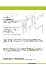
Lay the TURNY flat on a table with the front side up. The book support bar (fig.2/3)
can now be slid from below onto the TURNY, such that the pins fit into the slots on
the back side of the TURNY. The book support bar is properly installed when on the
front side of the TURNY the same row numbers are visible on both sides. The wire
for the book support bar should be on the right hand side.
-
Before the TURNY is ready to use, you need to check several
features and connect several plugs. Do not use force to insert a
plug into the wrong connector - each plug is designed differently,
so that it will only fit into its proper connector. In the following
list of connections, the numbers quoted correspond to the numbers
in fig.1, numbers 4-6 (the back side of the TURNY).
-
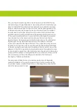
Place the TURNY on a flat surface, opening the support clip on the
back as far as possible to ensure the stability. The turning arm of
the TURNY is mounted on the motor through a friction clutch.
Normally the arm will move whenever the motor runs. If you stop the arm, holding it by
hand, the motor will continue to run and the clutch will slip. Thus, it is possible to move
the arm without damaging the TURNY.
The construction of the bottom plastic flap is identical. However, the construction of
the top flap is different and must not be moved by hand. This would cause damage
which can only be repaired by the manufacturer! If the TURNY is used in accordance
to this manual there will be no need to move either the arm or the flaps by hand.
-
Now plug the power supply (fig.1/10) in and turn the TURNY using the power switch
(fig.1/3) on. The red LED at the upper left corner will blink 4 times and then shine
constantly. If this does not happen, check that the power supply functions properly
and that the maschine is on. You may have to contact your supplier.
-
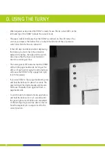
When the light shines steadily, the TURNY will bring itself
into the starting position, closing the flaps and positioning
the turning arm at the left hand side of the book. The middle
of the turning arm attachment should be just to the left of
the middle of the front board. The magnetic pin (fig.2/12)
above the adhesive roll (fig.2/13) ensures that the adhesive
roll does not touch the board. If this is not the case, please
read the related section in the chapter „Problems and Solutions“.


