


FDU-160i
FDU-160i Frequency Distribution Unit – Operation and Maintenance Manual
P/N 900000136 REV B
6
Original Manufacturer: General Devices Chassis Trak Type C300.
2.1.2
Power
Insert the power cord of the FDU-160i into an electrical socket to power up the unit. The
Power LED indicator will illuminate green.
If dual redundant power is required, connect both power sources to independent power
sources
2.1.3
Ethernet
Connect one end of an Ethernet patch cable to the FDU-160i Ethernet port J21. Connect
the other end of the Ethernet cable to the network with an Ethernet hub or switch.
2.1.4
Frequency Inputs
Connect a frequency input sources to the frequency input connectors J17 and/or J18.
Channel A Input is J18, and Channel B is J17.
2.1.5
Frequency Outputs
Connect the frequency outputs J1 through J16 to the coaxial infrastructure.
2.1.6
Console Port
Connect a DB-9F cable to port J20 in order to enable RS-232 access to the unit. (Straight,
pin3 is RX pin2 is TX)
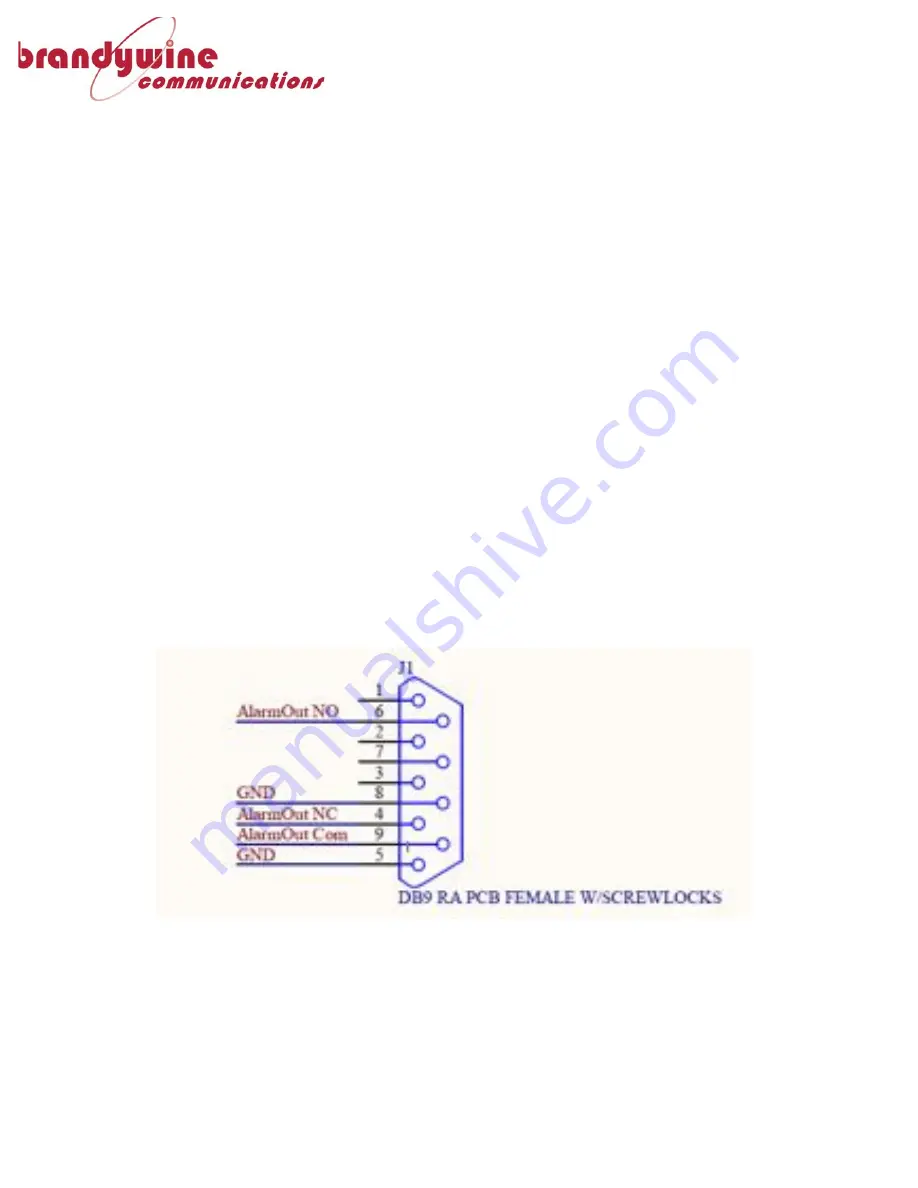
2.1.7
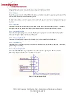
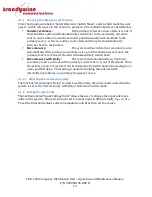
Alarm Output Port
Connect a DB-9M cable to port J19 to access the alarm output port. Please see the
following diagram for the pinout of the connector:
Figure 1 - Alarm output pinout


