16
Page 16
Burner Cleaning Procedure (cont’d)
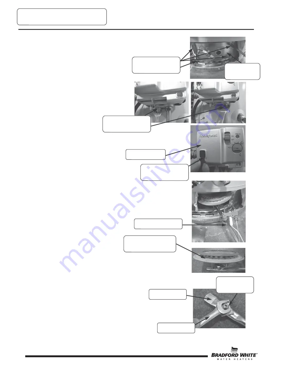
Step 5.
Remove the (4) 1/4” hex drive screws holding the
right side inner door in place.
Step 6.
Disconnect the pilot tube
using a 7/16” wrench and the main burner
feedline with a 3/4” wrench from the gas
control.
Step 7.
Disconnect the spark igniter/flame sensor wire
from gas control.
Step 8.
Remove the burner assembly from the combustion
chamber.
Step 9.
Thoroughly inspect the burner surface area and
burner port area and remove any loose debris.
Step 10.
Unscrew the burner from the main burner orifice.
Step 11.
Remove the main burner orifice from the main
feedline using a 1/2” wrench. Inspect the orifice and clean or
replace, if necessary.
Burner Maintenance
(4) 1/4” hex drive
screws
Right side
inner door
Pilot and main feed-
lines
Spark igniter/flame
sensor wire
Gas control
Burner assembly
Burner surface area
and burner ports
1/2” wrench
Main burner
orifice
Main feedline


