BOXLIGHT MimioClarity Technical User Manual Download Page 41


Page | 41 
 

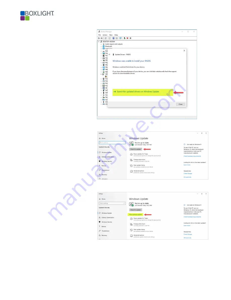
Update Drivers – RNDIS Window 


11.


Click on 

Search for updated 

drivers on Windows Update


12.


The window will change. 


Settings – Windows Update Window 


13.


Click the 

Check for Update

 box. 


Settings – Windows Update Window 


14.


Click on 

View optional updates


Summary of Contents for MimioClarity

Page 1: ...to four 4 microphones in any combination of teacher or student microphones Key Terms Paired when the microphone is paired with the amplifier the two devices have been introduced and have agreed to pa...

Page 2: ...phone 12 Muting the Teacher Microphone 12 External Microphone 12 External Device Line Input 13 Student Microphone 13 Pairing the Student Microphone 13 High Frequency OFF default setting when shipped 1...

Page 3: ...ext to Speech 31 Network Page Wired DHCP 32 Network Page USB 32 Network Page DNS 33 Network Page NTP 33 Setting the Time Zone 33 Setting a Time Server Pool Address 34 SIP Page Registering 34 Maintenan...

Page 4: ...ery word is heard by every student Best of all Boxlight technology does not rely upon a line of sight like IR receivers MimioClarity RF will not interfere with Wi Fi or Bluetooth frequencies Teacher M...

Page 5: ...d to amp via USB A Default Page up page down Inputs Output and Buttons Omnidirectional Mic Picks up sound with equal gain from all sides or directions On Off Button Power the microphone on and off But...

Page 6: ...roximately 2 hours The microphone can be used while charging Dimensions and Weight Overall Dimensions W x H x D 3 5 x 1 754 x 75 99mm x 46mm x 19mm Net Weight 2 2 oz 62g Environmental Storage Temperat...

Page 7: ...e can also be used to distribute media through the 3 5 Audio Line Input as well as capture group conversations when toggled on Student Microphone Frequency DECT 1 9 GHz Does not interfere with Bluetoo...

Page 8: ...es Push to Talk Button Push down to turn on microphone to capture voice like a CB radio Button is blue while charging Toggle to Talk Switch Switch to activate the microphone being continuously on Audi...

Page 9: ...th the microphones paired to the amplifier Connecting turning on the microphone so the audio can be heard in the classroom You will need to connect turn on your mic whenever you want to use it in the...

Page 10: ...ON 1 Make sure the amplifier has power the microphone button on the amplifier will be red 2 Press the Power button on the teacher microphone it will turn green 4 Once the Pair Connect button on the te...

Page 11: ...the Reset button next to the ETH port this is considered a soft reset This resets the processor but doesn t change the audio path or the mic status When you press and hold the Factory Reset button it...

Page 12: ...ed it will illuminate red and stay red until it is pressed again to unmute The mute button will also be illuminated blue while charging To mute the microphone press the mute button one time To unmute...

Page 13: ...k button on the student microphone at the same time then release The student microphone Pair Connect button will start blinking green and the power button on the amplifier will start blinking green Hi...

Page 14: ...o be connected each time it is powered on Using the Student Microphone The MimioClarity Student Microphone is simple to operate and is powered by two methods Press the power button to turn the microph...

Page 15: ...C Interface 1 x USB C Bottom side Interface with local computer Control I O 1 x 3 Pin Phoenix Connector RS 232 Audio Line In 3 Line In 3 5 Audio Line In With Control 2 x RJ 45 line level audio input...

Page 16: ...r speaker A B Connect to building paging system mutes all amplifier inputs in the event of a building page Power Pairing Button Turning on off and pairing the microphones ALD Button Uses near field ha...

Page 17: ...g speakers receive audio the Clarity amplifier will mute all audio When the building s paging speakers no longer receive audio the Clarity amplifier will no longer mute audio 3 5 Input s Connect the B...

Page 18: ...45 Input Wiring Diagram Inputs 4 5 This diagram applies to Inputs 4 and 5 RJ45 Output Wiring Diagram Output 1 This diagram applies to Output 1 RJ45 MIC GPIO 1 3 This diagram applies to wired MIC and G...

Page 19: ...efault the USB IP address is pre set Accessing the amplifier over the network will require the use of the speakers or a network scanner e g Advanced IP Scanner From the factory the Clarity Amplifier i...

Page 20: ...mmended using the USB C port or via the network The following instructions will walk the user through accessing the amplifier using both methods USB C 1 Using the USB C port adjacent to the Network po...

Page 21: ...Page 21...

Page 22: ...using both methods USB C 1 Using the USB C port adjacent to the Network port connect the amplifier to the computer 2 Open your favorite web browser and type the following IP address 192 168 123 1 Netw...

Page 23: ...amplifier requires the use of a pairing code This feature may be disabled by removing the check in the Use pairing code check box The following instructions demonstrate pairing a Bluetooth device wit...

Page 24: ...luetooth device through the Clarity amplifier Note Volume is ultimately controlled by the input level of Bluetooth device Input Page User and IT Accounts The input looks the same for both the user and...

Page 25: ...Page 25...

Page 26: ...Page 26...

Page 27: ...and will not be addressed in this manual Input 3 Typically connect to the Boxlight IFP Inputs 4 5 are open for other audio inputs e g MP3 player computer audio etc Note Input settings are typically se...

Page 28: ...addressed in this manual Outputs 1 and 2 phoenix connectors are typically connected to the speakers in the classroom Recommended setting for these two outputs is 90 to 100 Final audio level will be ad...

Page 29: ...nd digital equalizer with 5 presets By default the digital equalizer EQ is set to the OFF position In the OFF position the amplifier will play the source audio as it is received 1 To use the EQ it mus...

Page 30: ...Page 30...

Page 31: ...ng instructions will walk you through the process of setting this feature to the OFF position Note the process is the same for all three connections 1 Click the ON OFF toggle setting to toggle OFF 2 C...

Page 32: ...the network s Gateway address 5 Click the Submit button Note Type the new static IP address in the web browser to access the Clarity amplifier Network Page USB By default the Clarity amplifier USB con...

Page 33: ...internal clock is set to the local time zone the time zone must be set In addition should the owner of the system choose to use an alternate time server the Clarity amplifier allows for the time serv...

Page 34: ...time server address in the Pool 2 field 3 Click the Submit button SIP Page Registering The Clarity amplifier has the ability to register with a SIP server to receive incoming and make outgoing calls...

Page 35: ...a is correct the Clarity amplifier will show as registered Maintenance Page The Clarity amplifier allows the Firmware to be field upgraded over the network or the USB cable Should a field upgrade be r...

Page 36: ...he upper left corner of the screen adjacent to the logo of all Clarity pages and is the name that will be displayed on a network scan This name is to help identify an individual amplifier when there a...

Page 37: ...password in the Password field 2 Type the new password in the Password confirmation field 3 Click the Submit button Note The instruction for changing the IT user is the same Diagnostics High Frequenc...

Page 38: ...h a fully patched Windows 10 computer via the USB cable and the computers web browser NOTE It is best that the target computer is fully patched with all available updates Contact your computer s manuf...

Page 39: ...w 3 Note the status of the Device Manager Window when it loads on the screen Device Manager Window 4 Plug the USB C cable into the Clarity Amplifier and the computer 5 Notice the New Device displayed...

Page 40: ...r Window 6 Place the mouse over the text reading RNDIS 7 Right click and select Update Driver 8 A new window will appear Update Drivers RNDIS Window 9 Click on Search automatically for drivers 10 A ne...

Page 41: ...NDIS Window 11 Click on Search for updated drivers on Windows Update 12 The window will change Settings Windows Update Window 13 Click the Check for Update box Settings Windows Update Window 14 Click...

Page 42: ...Gadget Serial b Acer Incorporated Other hardware Acer USB Ethernet RNDIS Gadget c Acer Incorporated Other hardware Acer Composite USB Device 17 Click the Download and install button Device Manager Wi...

Page 43: ...Page 43 Device Manager Window 20 Open the computer s web browser 21 Type the default IP address of the amplifier in the web browser 22 The user interface of the amplifier will display...

Reviews: