background image

19

Projecting HDTV

Determine the cables you’ll need (refer to the table on page 10 if 
necessary). This depends on what type of output is coming from 
the tuner (remember, you cannot directly connect the coaxial 
cable that enters your house from a cable or satellite company, 
the signal must pass through a tuner first.) Also, determine if you 
want the sound to come out of the projector or out of your own 
audio system. You can connect the audio directly to the projector 
to get sound from the 3-watt onboard speaker, or you can con-
nect it to your stereo’s receiver to get sound from your own 
speakers.

NOTE:

 If needed, you can pur-

chase longer cables at your local 

electronics store.

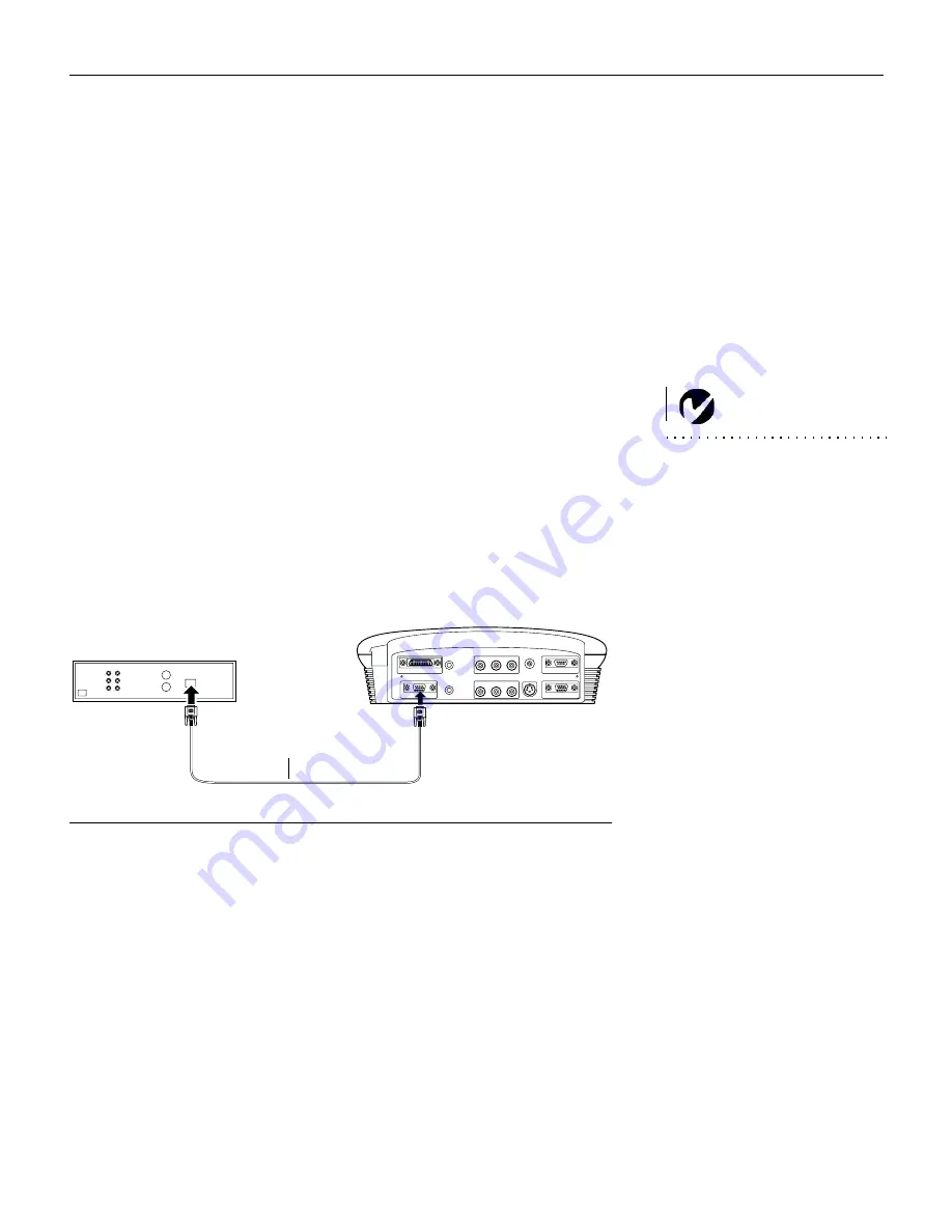
If your HDTV tuner has a 15-pin VGA output:

1

Plug one end of the VESA cable to the VGA connector on your 
HDTV source (Figure 18). This connector may be labeled “To 
Monitor.”

2

Plug the other end of the cable into the VESA connector


(labeled PC 2) on the projector.

F

IGURE

 18

Connecting the projector to an HDTV source using the VESA cable

3

If you want sound from the projector’s speaker, plug the A/V 
cable’s white connector into the left “audio out” connector on 
your tuner. Plug the cable’s red connector into the right 
“audio out” connector on the tuner.

4

Plug the A/V cable’s other white connector into the white 
“audio L” connector on the projector. Plug the cable’s other 
red connector into the red “audio R” connector on the projec-
tor. The yellow connectors on the A/V cable remain unused.

VESA
cable

Summary of Contents for Cinema 12SF

Page 1: ...Cinema 12SF USER S GUIDE USER S GUIDE 5466User qxd 11 1 01 11 36 AM Page 1...

Page 2: ...Cinema 12SF User s Guide 5466User qxd 11 1 01 11 36 AM Page 2...

Page 3: ...Copyright 2001 by BOXLIGHT Poulsbo Washington All rights reserved...

Page 4: ...cular installation If this equipment does cause harmful interference to radio or television reception which can be deter mined by turning the equipment off and on the user is encouraged to try to cor...

Page 5: ...tive 73 23 EEC Amended by 93 68 EEC Safety EN 60950 1992 A1 A2 A3 A4 1997 November 2001 Trademarks Apple Macintosh and PowerBook are trademarks or registered trademarks of Apple Computer Inc IBM and P...

Page 6: ......

Page 7: ...ape 15 Projecting HDTV 19 Projecting a video game 21 Connecting a camcorder 21 Connecting a Computer 23 Displaying your Computer Source 24 Turning Off the Projector 26 Using the Projector 27 Basic Ima...

Page 8: ...Replacing the Projection Lamp 49 Cleaning the Projection Lamp Filter Screens 52 Replacing the Batteries in the Remote Control 53 Troubleshooting 54 Appendix 61 Specifications 61 Accessories 62 Audio...

Page 9: ...ons or practices that could result in damage to your equipment Safety Symbols Attention For information about usage of a feature please refer to the User s Guide Warning Hot surface Do not touch An ar...

Page 10: ...tion Don t place the projector on a hot surface or in direct sunlight Caution Do not drop the projector Transport the projector in a Studio Experience approved case see page 63 for a list of cases Imp...

Page 11: ...SVGA resolution of the Cinema 12SF s projected image is 800x600 The projector is compatible with screen resolutions up to 1024x768 If your computer s screen reso lution is higher than 1024x768 reset i...

Page 12: ...on connecting and operating the projector refer to this User s Guide FIGURE 1 Shipping box contents 1 Projector lens cap 6 Enhanced Connectivity module 2 Soft carry case 7 Computer cable 3 User s Gui...

Page 13: ...view of projector FIGURE 3 Back view of projector FIGURE 4 Back view of projector with Enhanced Connectivity Module attached focus ring zoom ring power cord connector height adjustment button connect...

Page 14: ...in direct sunlight or extreme cold for extended periods of time If this happens allow it to reach room temperature before use Transport the projector in a vendor approved hard or soft case Do not sub...

Page 15: ...rojector on the ceiling refer to the installation guide that comes with the Ceiling Mount Kit for more information To turn the image upside down see Ceiling Project on page 46 Studio Experience recom...

Page 16: ...lue is 113 7 for 4 3 mode FIGURE 6 Projection angle in 16 9 mode 3 Make sure the projector is unplugged and your equipment is turned off WARNING Do not place the projector on a tablecloth or other sof...

Page 17: ...enhanced connectivity module When you attach it to the back of the projector it looks like this FIGURE 8 Connector panel with enhanced connectivity module attached This module adds all the connectivit...

Page 18: ...ack of the projector then press the computer connector into the projector To remove the module press down all the way on the textured lever on the top left of the module to release the latch then slid...

Page 19: ...16 9 Most regular TV shows are 4 3 most movies are 16 9 If you select 4 3 and play TV the image will fill the screen If you select 16 9 and play HDTV the image will fill the screen How ever if you se...

Page 20: ...Connector Label on Projector Source name on Screen Standard Broadcast TV not HDTV via cable digital cable satellite TV DirectTV Composite video S video Component Video video 2 video 1 video 3 Video 2...

Page 21: ...sound from your own speakers If your TV tuner has S video output 1 Plug one end of the S video cable to the S video out connec tor on your tuner Figure 12 This connector may be labeled To Monitor 2 Pl...

Page 22: ...recommended The LED on the top of the projector Figure 24 on page 30 lights green Now you are ready to turn on the equipment and watch TV 6 Remove the projector s lens cap 7 Turn on the lamp by press...

Page 23: ...the pro jector s on screen menus To open the menus press the menu select button on the keypad or remote then select the Display or Image sub menu For more information about the menus see page 33 If t...

Page 24: ...from the projector s speakers plug the A V cable s white connector into the left audio out connector on your tuner Plug the cable s red connector into the right audio out connector on the tuner 4 Plug...

Page 25: ...to the S video out connec tor on your video device Figure 15 This connector may be labeled To Monitor 2 Plug the other end of the cable into the S video connector labeled video 1 on the projector FIGU...

Page 26: ...commended The LED on the top of the projector Figure 24 on page 30 lights green Now you are ready to turn on the equipment and watch a DVD or tape 6 Remove the projector s lens cap 7 Turn on the lamp...

Page 27: ...mote to adjust the image s shape See page 31 9 Insert the tape or disk you want to play then start playing it Some DVDs start automatically some require you to select Play Movie from the startup scree...

Page 28: ...FIGURE 17 Connecting the projector to a video player using the audio video A V cable 3 If you want sound from the projector s speaker plug the A V cable s white connector into the left audio out conne...

Page 29: ...r cables at your local electronics store If your HDTV tuner has a 15 pin VGA output 1 Plug one end of the VESA cable to the VGA connector on your HDTV source Figure 18 This connector may be labeled To...

Page 30: ...TV image You can select a default source to determine which source the projector examines first during power up for active video see Default Source on page 45 If necessary adjust the zoom or focus of...

Page 31: ...he instruc tions in the previous section to connect and display these sources Projecting a video game To play a game from a video machine Connect your equipment as described in Connecting a Video Devi...

Page 32: ...conds for the projection lamp to reach full power and project the image again See page 32 for details on standby mode NOTE Lamp life will be extended if you turn the power off then wait 1 minute while...

Page 33: ...p computers are listed in the Customer Support section of our website 2 Plug the other end of the computer cable into the video con nector on your computer If you are using a desktop com puter you nee...

Page 34: ...pad or remote A tone sounds when you press the button and the LED blinks green while the software initializes When initializa tion is complete the LED lights solid green and the startup screen appears...

Page 35: ...Windows automati cally locates the driver If this driver has been removed reload the driver using your Windows operating system CD When Windows finds the driver you are ready to install it Click Next...

Page 36: ...r the degamma page 44 Turning Off the Projector If you want to turn off the projector for a short period of time press the standby button on the keypad or remote This blanks the screen for fifteen min...

Page 37: ...screen 2 If the image is out of focus rotate the focus ring page 27 3 If the image is not square adjust the keystone page 31 4 If the colors don t look right adjust the brightness contrast tint color...

Page 38: ...nd hold the elevator button Figure 21 2 Raise the projector to the height you want then release the button to lock the elevator foot into position FIGURE 21 Adjusting the height of the projector 3 If...

Page 39: ...f the projector The range for optimum operation is about 25 feet If you point the remote at the projection screen the dis tance to the screen and back to the projector must be less than or equal to 25...

Page 40: ...2 Composite PC 2 Component and PC 2 Analog Press the menu select button to open the on screen menus Press menu select again while Exit is highlighted to close the menus The menus automatically close a...

Page 41: ...ns act like the page up and page down buttons on your computer s keyboard You can use them to advance through a slide show in PowerPoint presentations To use this feature you must purchase an optional...

Page 42: ...keypad See page 42 for details Zoom remote only This allows you to zoom in and out on a part of the image Standby When you press standby the display and audio turn off and a blank screen is displayed...

Page 43: ...arrow LEDs around the buttons light green to indicate the change Press the corresponding buttons to move the cursor up and down or use the arrow buttons on the remote The selected menu is highlighted...

Page 44: ...page 31 for details on keystone adjustments 1 Press the down button to highlight Keystone then press menu select Use the left and right arrows to adjust the key stone setting Press menu select to acce...

Page 45: ...he color then press menu select to accept your changes Sharpness This setting adjusts sharpness of a video image 1 Use the up and down arrows to highlight Sharpness press menu select use the arrows to...

Page 46: ...nd down arrows to highlight Volume press menu select use the arrows to adjust the volume then press menu select to accept your changes Mute This mutes the sound 1 Use the up and down arrows to highlig...

Page 47: ...options The goal is to show the most detail on the screen while preserving the ratio of width to height Often the terms wide screen letterbox or letterbox or enhanced for widescreen or anamorphic appe...

Page 48: ...38 U s i n g t h e P r o j e c t o r Table 1 Resize options for various setups If you have this source and this screen aspect choose this resize option to get this image...

Page 49: ...4 3 screen with Resize set to Enhanced Widescreen Widescreen Letterbox NOTE A source that says Wide screen usually means the same as Widescreen Letterbox FIGURE 31 16 9 input on 16 9 screen with Resi...

Page 50: ...40 U s i n g t h e P r o j e c t o r Standard FIGURE 32 4 3 input on 16 9 screen with Resize set to Standard Native Resize menu select menu select 4 3 image input 4 3 image on 16 9 screen...

Page 51: ...e keystone 0 zoom mode Video Standard NOTE If you already know the video standard used in your geo graphical area it s often best to manually select it 1 2 3 4 3 4 516 516 7 516 3 516 8 417 417 516 7...

Page 52: ...omputer Sources menu select 7 menu select FIGURE 33 Image menu for computer sources Resize Resize Enhanced Widescreen 6 Widescreen Letterbox Standard Native Resize menu select menu select Zoom Zoom me...

Page 53: ...are available only for ana log computer sources The projec tor sets these options automatically for digital computer and video sources with no manual override 2 2 2 Auto image 2 1 1 2 7 menu select 2...

Page 54: ...NOTE Your viewing preferences may vary Cycle through the degamma options and pick the one you like the best Degamma menu select menu select Color Space Standard 1 2 4 75 8 4 8 4 8 Color Space Standar...

Page 55: ...4 menu select 7 4 menu select 4 FIGURE 35 Control menu Auto Source A 2 A 2 source data video Auto source menu select Default Source 2 54 1 54 54 1 4 4 Default source menu select menu select Standby T...

Page 56: ...o j e c t o r Advanced Menu FIGURE 36 Advanced menu Rear Project Rear Project 2 2 Rear Project menu select Ceiling Project Ceiling Project 2 2 4 5 2 menu select Display Messages A A A 93 9 1 Display...

Page 57: ...47 Reset menu select 6 4 5 2 1 Language Menu FIGURE 37 Language menu 5 4 C D 1 5 menu select 7 6 menu select 6 2 5 menu select 5 menu select 7...

Page 58: ...n g t h e P r o j e c t o r Status Menu 7 menu select FIGURE 38 Status menu Lamp Hours Used 9 5 2 6 Video Standard Computer Resolution computer sources only Source 54 1 54 54 1 54 4 4 4 4 Software Ve...

Page 59: ...2 1 1 E 1 E 1 2 6 3 2 Replacing the Projection Lamp WARNING To avoid burns allow the projector to cool for at least 30 minutes before you open the lamp module door Never extract the lamp module while...

Page 60: ...s small glass fragments may be generated The lamp module is designed to contain these fragments but use caution when removing the lamp module FIGURE 39 Removing the lamp door CAUTION Never operate the...

Page 61: ...51 5 6 FIGURE 41 Removing the lamp module WARNING Do not drop the lamp module or touch the glass bulb The glass may shatter and cause injury 6 7 5 2 8 9 2 2 10 5 power 2 11 volume source volume B...

Page 62: ...52 M a i n t e n a n c e T r o u b l e s h o o t i n g Cleaning the Projection Lamp Filter Screens B8 1 9 5 2 6 2 1 G FIGURE 42 Lamp module screens 3 2 4 screen screen...

Page 63: ...53 Replacing the Batteries in the Remote Control 1 2 5 3 4 111 7 5...

Page 64: ...54 M a i n t e n a n c e T r o u b l e s h o o t i n g Troubleshooting 6 2 2 2 Table 2 LED behavior and meaning LED color behavior Meaning 2 2 2 2...

Page 65: ...7 2 2 The projector is not run ning LED is lit green 7 2 Projector is running LED lit green but nothing appears on projection screen 7 2 2 Projector is running LED blinking series of 3 fast amber but...

Page 66: ...56 M a i n t e n a n c e T r o u b l e s h o o t i n g No sound 1 2 9 1 2 Lamp seems to be getting dimmer 9 5 2 6 Lamp shuts off 1 0 2 7 1 2 4 B 7 888 888 Table 3 Problem with the projector...

Page 67: ...ge is too wide or narrow for screen 1 2 2 1 2 1 2 Image is not square 1 2 Image is noisy A Color or text not being pro jected 2 9 Image and menus are reversed left to right 2 5 2 4 2 9 5 2 Image and m...

Page 68: ...nt source appears greenish 8F8 9 8 8 9 8 F8 9 8 Image appears torn 9 Table 4 Problem with a video image Table 5 Problem with a computer image Symptom Remedy Only the start up screen displays 7 9 8 H 7...

Page 69: ...e screen resolution is not right 7 8 F Image is noisy or streaked 1 2 Auto Image 91 3 Auto Image 2 97 97 E Projected colors don t match the computer or video player s color C 2 1 2 9 9 B 94 Image appe...

Page 70: ...60 M a i n t e n a n c e T r o u b l e s h o o t i n g...

Page 71: ...operating 0 to 20 000 feet 6 096 meters Humidity Operating and non oper 10 to 95 relative humidity non condensing Dimensions 10 4 x 11 1 x 3 3 inches 264 x 283 x 85 mm with module 10 4 x 12 1 x 3 3 in...

Page 72: ...untry Standard Accessories ship with the projector Quick Start card User s Guide Soft Case Shipping Box VESA Computer Cable 6 ft 1 8 m Audio Video Cable 6 ft 1 8 m S Video Cable 13 ft 4 m Remote Proje...

Page 73: ...Theatre Screen 80 diagonal 4 3 ratio Deluxe Insta Theatre Screen 60 diagonal 4 3 ratio Wall or Ceiling Mountable Projection Screens Projection Lamp Module High definition S video Cable High definition...

Page 74: ...e Width inches m Maximum distance feet m Minimum Distance feet m 60 1 5 52 2 1 33 9 1 2 77 7 4 2 26 72 1 8 62 6 1 59 10 9 3 32 8 8 2 68 84 2 1 73 1 1 86 12 7 3 87 10 3 3 14 90 2 3 78 3 1 99 13 6 4 15...

Page 75: ...istance feet m 60 1 5 48 1 22 8 9 2 71 7 2 2 19 72 1 8 58 1 47 10 7 3 26 8 7 2 65 84 2 1 67 1 70 12 5 3 81 10 1 3 08 90 2 3 72 1 83 13 4 4 08 10 9 3 32 100 2 5 80 2 03 14 9 4 54 12 1 3 69 120 3 1 96 2...

Page 76: ...66 A p p e n d i x...

Page 77: ...67 INDEX Numerics A B 1 3 2 2 8 1 4 5 2 F 7 F F 5 2 F 8 B 1 7 F F 1 B B BB BB 2 D 7 5 C 8 B B 2 2 F 8 B B 2 B 2 4 7 1 4 4 2 B 7 7 B...

Page 78: ...68 I n d e x 8 B B F 2 4 1 D 4 4 D 1 7 F F 7 7 E 8 4 7 2 8 B F B H 2 8 5 B I 7 2 B B F F H 1 B 5 B 7 B 7 B A K F K...

Page 79: ...69 L B B B B8 B B 6 B B 6 B 6 B B M 7 B 7 B 7 B F N 3 3 4 O B P 516 5 F F H F 8 5 5 2 F 2 F 2 2 B 2 F B B F R 2 F 2 5 5 BB 2 B B 2 B 2 B 8...

Page 80: ...70 I n d e x S 1 417 H F B8 T 0 1 2 B 2 F 2 V B 5 B 4 2 F W B Z K...

Page 81: ...8 WARRANTY LIMITATION AND EXCLUSION 1 13 A AI6 71I 707 6 1 6 A 5 A 04 1 13 I 3 A36 A 5 A 04 50 4 1 A7 AI6 A 1 AI6 10 A K 66 AI6 6 5 AI6 5 5 5 5 6 5 5 9 5 6 1 6 5 5 5 6 5 5 6 5 6 DISCLAIMER OF UNSTATED...

Page 82: ...I6 6 1 6 3 4A3 14 3 A 03 13 1 13 3 3 6 34 A A 166 3A I4 0 3 A 17A03 A 50 4 1 5 4 51 50 4 1 13 03 3A 4 407 134 166 AI6 6 1 6 A 5 4 16 3 4 34 3 16 A 4A3 N0 3 16 171 A 6A 5 A 6A 30 A 6A 1 3 5 4 1 A 5 A 0...

Page 83: ...ma 12SF Boxlight 19332 Powder Hill Place Poulsbo WA 98370 7407 USA www boxlight com U S A and Canada 800 762 5757 International 360 779 7901 Printed on recycled paper 5466User qxd 11 1 01 11 36 AM Pag...

Reviews: