BOWIE PUMPS Eco-Seal Series Installation, Operation And Maintenance Manual Download Page 2


ES IOM Rev 1 

-

 5/13/2021


2


PUMP IDENTIFICATION


Pump serial number and model designation will be sup-
plied with each pump.  It is recommended that this data 
be recorded and filed for future reference.  This data 
should be supplied to a Bowie representative when re-
placement parts, repair work, or information pertaining 
to the pump is required. 


PUMP DATA


PUMP INFORMATION


Model No.: _____________________


Serial No.: _____________________


Date of Installation: _____________


PUMP DESCRIPTION


Eco

-

Seal pumps are based on our industry leading Signature Series of pumps but with one major difference:


 the pumps are 

engineered with a high performance lip sealing system for enhanced leak protection.


 The result:


 an affordable, long lasting, 

low maintenance bushing

-

design pump which meets more stringent environmental and safety standards.


There are three lines of Eco

-

Seal Series pumps:


 300 Eco

-

Seal –


the standard pump; 300 Eco

-

Seal S –


short drive neck for ac-

cess in tight spaces; 300 Eco

-

Seal ED –


extended duty.


PUMP DIMENSIONS, EXPLODED VIEWS, AND OTHER TECHNICAL INFORMATION 


All technical information, including pump dimensional diagrams, exploded views with part listings, and other technical information 
are available at www.bowiepumps.com. 


Noise levels for all pumps will not exceed 95dB at a distance of one 
meter from the pump.
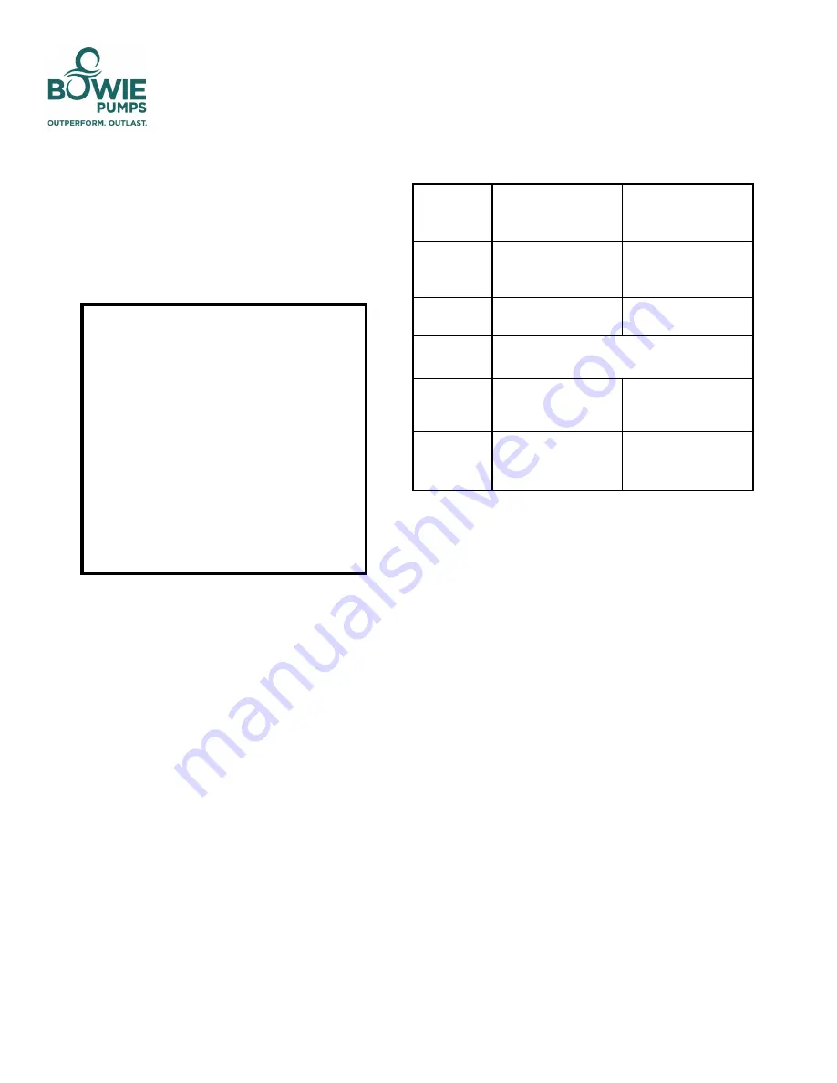
 

TECHNICAL DATA


* Pressures must be measured no farther than 

6” 

from the discharge port.  

Maximum operating limits are dependent on the materials of construction and 
application design requirements. 


Operating 


Criteria


Buna

-


Rubber Gears


Progressive Helical Steel 

Gears


Maximum 


Operating 


Temperature*


70°C


160°C


Maximum 

Speed*


500 RPM


750 RPM


Maximum 


Viscosity*


60000 SSU


Maximum 


Differential 

Pressure*


125 psi


150 psi


Maximum 

Working 


Pressure*


125 psi


150 psi


Summary of Contents for Eco-Seal Series

Page 1: ...e system MUST conform to all applicable local and national regulations and safety standards This manual is intended to assist in the in stallation and operation of the Bowie Eco Seal Series pumps and when possible kept with the pump Pump service shall be performed by quali fied technicians ONLY Service shall con form to all applicable local and national reg ulations and safety standards Thoroughly...

Page 2: ...ringent environmental and safety standards There are three lines of Eco Seal Series pumps 300 Eco Seal the standard pump 300 Eco Seal S short drive neck for ac cess in tight spaces 300 Eco Seal ED extended duty PUMP DIMENSIONS EXPLODED VIEWS AND OTHER TECHNICAL INFORMATION All technical information including pump dimensional diagrams exploded views with part listings and other technical informatio...

Page 3: ... lines and piping MUST be free of all leaks NOTICE Bowie pumps must be installed only in systems design by qualified engineering personnel Bowie pumps should only be installed in duties for which Bowie Pumps of Canada Ltd have specified the attributes of the pump System design must conform to all applicable regulations and codes and provide warning of all system hazards NOTICE PTO and hydraulicall...

Page 4: ...ng a surging vibration to the fluid system POWER TAKE OFF PTO DRIVE Bowie pumps may be driven by a PTO drive A direct drive shaft with a universal joint on each end of the shaft is used to connect the pump to the drive A sleeve joint can be used to compensate for any play caused by road conditions General guidelines for proper pump drive 1 The angle of drive shaft between pump and PTO must be NO L...

Page 5: ...ge line and reading the pressure gauge This pressure must be a minimum of 20 30 psi 1 4 2 1 Bar higher than the maximum system operating pressure or pressure relief plate setting and must not exceed 150 psi DO NOT operate the pump against a closed discharge valve for more than 15 seconds If adjustments need to be made refer to the Relief Valve Setting and Adjustment sec tion of this manual NOTICE ...

Page 6: ...ons with sticky fluids that solidify within the pump i e waxes adhesives etc use a fluid that prevents solidification of the fluid to facilitate flushing NOTICE Properly dispose of all waste fluids in ac cordance with appropriate codes and regu lations PUMP OPERATION Disconnecting fluid or pressure containment components dur ing pump operation can cause serious personal injury death or major prope...

Page 7: ...ngs Tighten the locking nut and replace the locking cap Selecting the CORRECT LOCKING CAP viewing the front plate of the pump To adjust flow pressure for CLOCKWISE shaft rotation a The drive shaft below the idler shaft Adjustments must be made to the RIGHT side spring b The drive shaft above the idler shaft Adjustments must be made to the LEFT side spring To adjust flow pressure for COUNTERCLOCKWI...

Page 8: ...s of grease applied approximately every four 4 operating hours in the front drive neck of the pump For all other grease fitting locations we recommend 1 2 ounces of grease applied every four 4 operating hours The actual amount of grease to be applied can be identified as the point when high re sistance to further greasing has been achieved For operating conditions above those specified refer to th...

Page 9: ...ore For storage longer than 6 months in addition to following the short term storage steps the following pro cedures should be carried out every 2 3 weeks 1 Rotate the pump several full revolutions to avoid the gears setting in the housing 2 If corrosion is present apply light oil to all rotating parts and repeat step 1 PREVENTATIVE MAINTENANCE Failure to set vehicle emergency brake and chock whee...

Page 10: ... or toxic fluids pump must be flushed before service PUMP DISASSEMBLY 1 Remove the two drain plugs 3318 from back plate 2 Remove the three end plugs 4308BF from the front and back plates 3 Remove secure wire from packing nut and packing nut itself 4301 4 Remove the quick change sleeve ECOEDSL and quick change containment seal 3325V from the Drive shaft 5 Remove all bolts on the back plate and remo...

Page 11: ...additional housing gasket on to hardened wear plate 10 Apply light oil on two seals and around the seal pockets in the back plate Insert one lip seal 3325 on to each of the two shafts ends Keep lips orientation toward the casing 11 Mount back plate with four bolts tightening in a cross pattern 12 Turn drive shaft to ensure proper meshing of gears and acceptable clearances between the gears and pla...

Page 12: ...ne Damaged or worn parts Pressure Relief Plate is set too low or attached incorrectly if installed Pump speed is too fast for viscosity or volatility of the liquid Pump not securely mounted Loose undersized piping and fittings Pump is too far from fluid source Improper drive or hydraulic connection Dry running the pump Excessive heat in the pump Excessive discharge pressure Cavitation Normal end o...

Page 13: ...ES IOM Rev 1 5 13 2021 13 CONTACT INFORMATION Bowie Pumps of Canada Ltd 9333 41 Ave T6E 6R5 Edmonton AB Tel 1 877 862 6943 Email info bowiepumps com ...

Reviews: