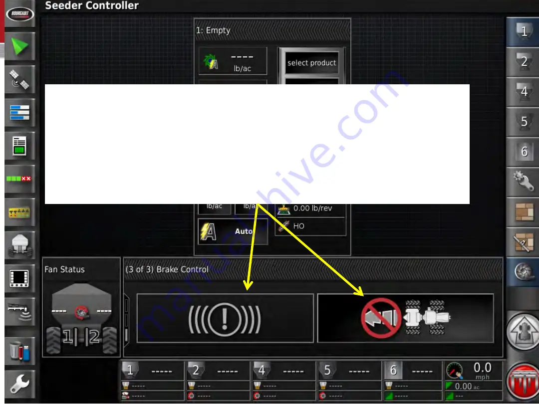
There are a couple of ways to test your surge breaks if equipped with
them.
•
Put a couple of large blocks behind the tank tires and slowly back up.
•
Or use the Surge Break Bleeding pump kit to pressure up the system,
all Bourgault dealers have this as a mandatory service tool kit.
(see the next slide for details on what you should see with 2019 and
newer X35 software)
Summary of Contents for 7000 Series
Page 1: ...Functional test for 7000 units with ASC ...
Page 3: ...Before starting the functional test you should fill out this form kuk ...
Page 6: ...Go to User Region Units and make sure the units are as indicated above ...
Page 8: ...Also in System Features Console make sure the XTEND is Enabled ...
Page 17: ...After selecting one of the 4 options above press the check mark ...
Page 18: ...Press the check mark to advance ...
Page 21: ...Press the green check mark to advance to section or a Drill Template ...
Page 22: ...Select Bourgault then press the check mark to advance ...
Page 23: ...Press the check mark to advance ...
Page 32: ...Select Replace to open the wizard for detecting the first ECU ...
Page 33: ...Read the warning and acknowledge it to advance ...
Page 34: ...Follow the instructions in the wizard and advance ...
Page 37: ...Follow the wizard and then advance ...
Page 38: ...Accept the ECU ...
Page 41: ...Follow the Wizard and advance ...
Page 42: ...Advance to next slide ...
Page 44: ...Follow the Wizard again ...
Page 45: ...Advance ...
Page 46: ...The Blockage is now designated EM 24 3 Review and accept ...
Page 48: ...Go to Pack Master and enable it if your drill is equipped with it ...
Page 49: ...Change the Control Type to Pack Force and enter Preset 1 and 2 as well as an INCREMENT ...
Page 50: ...Confirm drill model Then select opener type equipped on drill Example PHD or XTC ...
Page 51: ...If equipped with Blockage go to Implement Seeder Accessories Blocked Head and Enable it ...
Page 55: ...Boom 1 is full width ...
Page 56: ...Our unit has dual boom section control so boom 2 is the Seed section control boom ...
Page 57: ...Boom 3 is Fertilizer section control ...
Page 60: ...For our demonstration we matched up the NH3 sections to the granular sections ...
Page 62: ...Enable the VIRTUAL SECTION SWITCHBOX ...
Page 66: ...Move over to Drive Setup and enter the type of auger in each tank with a metering auger ...
Page 68: ...If equipped with NH3 or Liquid enter the tank CAPACITY and the on and off timings ...
Page 69: ...Enter the NH3 Liquid CALIBRATION FACTOR ...
Page 71: ...If your system has integrated scales you click on DETECT NEW ECUS ...
Page 72: ...After detecting the new ECU press the check mark to advance ...
Page 74: ...The above settings are default settings ...
Page 77: ...This is where you can enable an audible click for the above functions if desired ...
Page 83: ...Pull all of your products from the Bourgault list and advance the Wizard ...
Page 85: ...Select PRODUCT NAME to give a new custom name ...
Page 87: ...Advance the slide ...
Page 90: ...Select the running man to go back to the operating screen ...
Page 92: ...Ensure all of the Tanks Fans and Speed are displayed ...
Page 93: ...While this screen is up press on Tank 1 layout to configure the Tank 1 displayed items ...
Page 94: ...Set all of your Tanks to display Application Rate Motor Load and Metering RPM ...
Page 98: ...Expand each tank and click on select product ...
Page 101: ...Deselect the tanks on the right and select the calibration icon Enter a MANUAL SPEED ...
Page 102: ...Select the GPS Position mini view to verify that the monitor is receiving GPS ...
Page 104: ...Name the Client Farm and Field Next press the check mark in the green box ...
Page 105: ...Name the Job FUNCTION TEST then press select check mark in the green box ...
Page 106: ...Press the green box with the check mark ...
Page 108: ...If the Master icon is Red lower right corner press it to see what is not ready ...
Page 109: ...With both fans engaged make sure you have RPM displayed for both ...
Page 111: ...2300 psi to get 6000 rpm No more than 450 psi back pressure ...
Page 113: ...Enter Calibration ...
Page 114: ...Enter Automatic Calibration ...
Page 115: ...Advance the wizard ...
Page 122: ...Enter the Configuration menu then select Pack Master Calibration ...
Page 124: ...Follow the wizard for step by step instructions ...
Page 127: ...Enter the Packing Force lbs from the chart and advance the wizard ...
Page 129: ...Enter the Packing Force lbs from the chart and advance ...
Page 130: ...Pack Master should be calibrated ...
Page 133: ...Repeat the Pack and Lift Master tests from this screen ...
Page 146: ...Go back to the operating screen and enter the inventory manager ...


