


4-4
255 Conquest
Section 4 • Electrical System
R
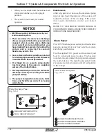
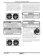
Component breakers
Component reset breakers are .located above the
equipment switches on the control station switch
panel (See fi g. 2.14.1) and on the battery switch panel
in the aft starboard compartment (See fi g. 4.2.1). In
the event of a loss of power, determine and correct
the problem before resetting the breaker at this
panel. Should a circuit breaker trip repeatedly, have
a qualifi ed electrician correct the cause of the trip.
Never reset a breaker without fi rst determining
and correcting the cause of the trip. Should
a circuit repeatedly trip, have a qualified
electrician determine and correct the cause.
!
CAUTION
Fuse Block
There is a fuse block located on the underside of the
control station. Access can be gained through a hatch
on the aft starboard wall of the cabin.
In the event you need to replace a fuse, use only the
same amperage as the original. It is recommended
that you carry spare fuses.
If a fuse is replaced with one of lower amperage, it
will not be suffi cient to carry the electrical load of the
equipment it is connected to and will cause nuisance
fuse failure or breaker tripping.
If a fuse is replaced with one of higher amperage,
it will not provide adequate protection against an
electrical malfunction and will create a fi re hazard.
Optional Fuse Block
Use of higher amperage fuses or breakers is a
fi re hazard.
Use fuses and breakers having the same amperage
rating as the original or as specifi ed.
!
WARNING
If equipped with the optional hardtop with electronics
box, there is a second fuse block located on the port
side of the electronics box interior.
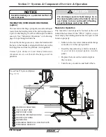
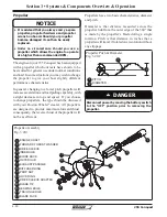
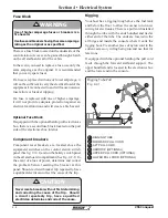
Rigging
Your boat has a rigging trough above the fuel tank
and below the
fl oor to allow the owner to run new
wiring for electronics. There is a pull cord installed
through the tube with the ends bundled and tied at
either end of the tube. The ends are located in the
aft bilge and inside the console where it exits the
rigging boot. Tie another piece of nylon cord to the
current accessory wiring being run and use that for
later runs.
If equipped with the optional hardtop the pull cord
feeds through the forward starboard support. The
upper bundled end is located in the electronics box
and the lower end in the console.
Rigging Tube/Pull
Fig. 4.4.1
RIGGING TUBE
FORWARD PULL CORD
AFT PULL CORD
HARDTOP (OPTIONAL)
UPPER PULL CORD (OPTIONAL)
LOWER PULL CORD (OPTIONAL)
1
2
3
1
4
2
6
5
3
4
5
6
Summary of Contents for 255 Conquest
Page 2: ......
Page 18: ...xviii 255 Conquest R THISPAGE INTENTIONALLY LEFT BLANK ...
Page 90: ...4 6 255 Conquest Section 4 Electrical System R Switch Panel Diagram Fig 4 6 1 ...
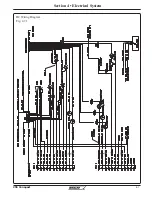
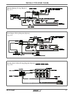
Page 91: ...4 7 Section 4 Electrical System 255 Conquest R DC Wiring Diagram Fig 4 7 1 ...
Page 94: ...4 10 255 Conquest Section 4 Electrical System R THIS PAGE INTENTIONALLY LEFT BLANK ...
Page 106: ...5 12 Section 5 Care Maintenance R 255 Conquest THIS PAGE LEFT INTENTIONALLY BLANK ...


