background image

T

u

n

in

g

T

h

e

A

m

p

li

fi

e

r

-

S

u

b

w

o

o

fe

r(

s

)

8

Tuning The Amplifier - Subwoofer(s)

1) Head Unit

The head unit should have all controls such as bass, treble, balance, and fader
set to the flat or centered position. The volume control should be at the 
minimum setting. If the head unit has any equalization or bass management
features such as boost, they should be deactivated at this time. Turn head unit
on, and verify that the Blue status LED (logo) is illuminated on the amplifier.

2) Volume

With the chosen musical track playing, turn the head unit volume control up
until the maximum level of undistorted signal is heard from the speakers. For
most head units, this will be at the end of the volume control range.

WARNING!

A distorted signal from the head unit sent to the amplifier can 

cause speaker failure at higher listening levels.

3) Input Sensitivity Control (Gain)

Turn control (refer to the diagram on page 3) all the way counterclockwise 
(minimum position). In this position, the amplifier will be less sensitive to the
input signal from the head unit. Slowly rotate this control clockwise until 
maximum undistorted playing level is heard from the subwoofer(s). Listen
closely for faults such as bottoming from the subwoofer(s). If fault is detected,
rotate input sensitivity control counterclockwise until fault is eliminated. At this
point, the maximum undistorted subwoofer playing level has been defined.

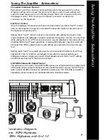
Configuration and Connection Diagram: 

Front & Rear Speakers - 80Hz Highpass

Subwoofer - 80Hz Lowpass, 35Hz Highpass, and Q of 1.2

Summary of Contents for GTA 1105

Page 1: ...High Performance 5 Channel Amplifier GTA...

Page 2: ...x 4 N A 4 Ohm Mono 250 Watts x 2 250 Watts x 1 2 Ohm Mono N A 400 Watts x 1 Impedance Stability 2 St 4 Mono 2 Frequency Response 3dB 10Hz 50kHz 10Hz 150Hz Signal to Noise Ratio 90dB 90dB A Weighted T...

Page 3: ...0Hz cont variable GTA RSL Port Remote Gain Speaker Output Block Front and Rear Speakers Speaker Output Block Subwoofer Status LED Blue Normal Red Fault Mode Fuses Replace with same value only refer to...

Page 4: ...system Wire Routing Do not run the power wire near any low level signals or audio cables such as the RCAs from the head unit Noise can be introduced into the amplifier when this occurs It is helpful...

Page 5: ...Tighten the 12v and GND terminals with the supplied 4mm hex wrench to secure the wire into the terminals If the power wire must be routed through a drilled or existing hole use a nylon panel grommet...

Page 6: ...nt to the speaker outputs If over excursion is detected from speakers move the switch to HP and slowly rotate clockwise until over excursion is eliminated 4 Head Unit The head unit should have all con...

Page 7: ...Rotate the crossover control fully clockwise refer to the diagram on page 3 The highpass crossover point is now set at 200Hz Q Tune should be set to off Slowly rotate the input sensitivity control clo...

Page 8: ...ad units this will be at the end of the volume control range WARNING A distorted signal from the head unit sent to the amplifier can cause speaker failure at higher listening levels 3 Input Sensitivit...

Page 9: ...s You may find while setting the Q Tune that over excursion may be detected in the subwoofer s lowering the Q Tune input sensitivity or raising the highpass crossover point will eliminate this Minor a...

Page 10: ...longside power Amplifier Output Distorted Music not Recorded with Intentional Distortion Verify Source output to amplifier is not distorted Amplifier input sensitivity is correctly adjusted Amplifier...

Page 11: ...Notes 11...

Page 12: ...e is a trademark of Boston Acoustics Inc Specifications are subject to change without notice 2010 Boston Acoustics Inc All rights reserved Covered by patents issued and or pending 142 003890 0 Boston...

Reviews: