9
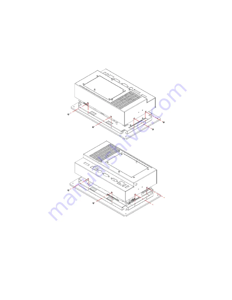
3.3 Back Cover Installation
1.
Follow the photo instructions to install the back cover onto the chassis.
Page 1: ...BPF 3307 7 Fanless Panel PC with Touch Screen 12V 24V DC In Provides Intel Atom processor 1 6GHz 2W AMP Stereo Speaker...
Page 2: ...ranted permission by BOSER Technology Co Ltd BOSER Technology Co Ltd reserves the right to change or improve the contents of this document without due notice BOSER Technology Co Ltd assumes no respons...
Page 3: ...pter 2 Unpacking 5 2 1 Opening the Delivery Package 5 2 2 Inspection 5 Chapter 3 Hardware Installation 7 3 1 HDD Installation 7 3 2 WLAN Device Installation 8 3 3 Back Cover Installation 9 3 4 Wall Mo...
Page 4: ...mpleted on a sample of the equipment identified below Equipment Class Information Technology Equipment Product Model Series BPF 3307 This Product Complies With EN55022 Class A for Radiated emissions E...
Page 5: ...damaged in anyway Do not insert objects into openings Do not immerse the product in water or permit liquids to spill inside Turn off power when the product is unattended or not in use Unplug product...
Page 6: ...y brightness decreases over time with use The expected operating lifetime of the backlight time to reach 50 initial brightness is 30 000 hours assuming continuous lit state at 25 degrees C Actual life...
Page 7: ...saction terminals POS home security systems ATM systems and voting machines etc It has a built in ultra low power consumption Intel Atom N270 processor 1 6GHz is responsed to demands of cost effective...
Page 8: ...6GHz The total power consumption of the system is under 27W merely It generates the best valve for both power usage and cost saving Without hard disk space and extra add on cards All of BPF series pa...
Page 9: ...x 2 5 SATA HDD space Watchdog Timer Software programmable time out intervals from 1 255 sec or 1 255 min Expansion 1 x Type III Mini PCI socket 1 x Mini PCIex1 socket Dimensions LxHxW 24 0 x 15 5 x 5...
Page 10: ...1905 Back light LED Touch Screen 7 resistive I O Interface External I O PS 2 KB MS 2 x COM LAN 2 x USB2 0 Rear I O 01 Power ON OFF 05 COM 1 02 DC In 06 LAN 03 KB MS 07 USB2 0 2 04 COM 2 1 3 Dimension...
Page 11: ...and carefully inspect it for any damage that might have occurred during shipment Ground the board and exercise carefully to prevent any damage to the board from static The BPF 3307 delivery package c...
Page 12: ...6 This page intentionally left blank...
Page 13: ...pter illustrates how to install components into the Panel PC system Please refer to the external interface of the board manual of the system 3 1 HDD Installation 1 Follow the photo instructions to ins...
Page 14: ...8 2 Follow the photo instruction to install the HDD_KIT onto the chassis 3 2 WLAN Device Installation 1 User can install the Network antenna module as below...
Page 15: ...9 3 3 Back Cover Installation 1 Follow the photo instructions to install the back cover onto the chassis...
Page 16: ...10 3 4 Wall Mount Kit 1 Follow the photo instructions to install the wall mount kit onto the chassis...
Page 17: ...e touch screen driver The following sections describe the installation procedures of driver based on WIN2000 operating systems Other operation systems may be slightly different 4 1 Resistive Type Touc...
Page 18: ...12 3 The next screen is Software License Agreement select I accept and click on Next 4 Click Install to begin the installation...
Page 19: ...tart the computer Click on Finish to exit the wizard 4 1 2 Installing Touch Screen Driver in WIN2000 1 Insert Utility CD Disk to your CD ROM drive The main menu will pop up as shown below 2 The screen...
Page 20: ...14 3 The next screen is Software License Agreement select I accept and click on Next 4 The next screen is Ready to Install the Program click on Install...
Page 21: ...rompt you to restart the computer Click on Finish to exit the wizard 4 1 3 PenMount Control Panel Calibrate To adjust the display with touch screen click on Calibrate button and follow the calibrate p...
Page 22: ...16 Draw Test or demonstrate PenMount touch screen operation also the touch location is shown on the display touch DRAW to start About It shows information about PenMount controller and driver version...
Page 23: ...ction there is a mouse icon shown in the right button place of screen It shows Left Button being as default for normal use change Right Left button by clicking the mouse icon box Blue area expresses w...
Page 24: ...18 This page intentionally left blank...