background image

English 

Installation and Safety Guidelines  Page 

5

pro.Bose.com

 Important 

Safety Information

12. Use only with the cart, stand, tripod, bracket, or table specified by the manufacturer or sold with the apparatus. 


When a cart is used, use caution when moving the cart/apparatus combination to avoid injury from tip-over.

13.  Unplug this apparatus during lightning storms or when unused for long periods of time to prevent damage  

to this product. 

14. Refer all servicing to qualified service personnel. Servicing is required when the apparatus has been damaged in any way such as power-

supply cord or plug is damaged; liquid has been spilled or objects have fallen into the apparatus; the apparatus has been exposed to rain 
or moisture, does not operate normally, or has been dropped. 

Do not attempt to  service this product yourself. Opening or removing covers may 

expose you to dangerous voltages or other hazards. Please call Bose to be referred to an authorized service center near you.

15.  To prevent risk of fire or electric shock, avoid overloading wall outlets, extension cords, or integral convenience receptacles. 
16.  Do not let objects or liquids enter the product – 

as they may touch dangerous voltage points or short-out parts that could result in a fire or electric shock.

17.  See product enclosure for safety related markings. 
18.  No naked flame sources, such as lighted candles, should be placed on the apparatus. 
19.  The mains plug is used to disconnect the device from the mains.
20.  The POWER indicator LED will illuminate green when the product has mains power. If power is applied and the LED is not illuminated, or if 

the LED is red, please send the unit for service.

Bose Corporation hereby declares that this product is in compliance with the essential requirements and other relevant provisions of  
Directive 1999/5/EC and all other applicable EU directive requirements. The complete declaration of conformity can be found at:  
www.Bose.com/compliance.

This Product meets the immunity requirements for the E2 class EN55103-2 directive.

Inrush current at cold start, 230V: 13.43A
Inrush current after interruption for 5 sec, 230V: 13.09A

Information about products that generate electrical noise

If applicable, this equipment has been tested and found to comply with the limits for a Class B digital device, pursuant to Part 15 of the FCC rules. 
These limits are designed to provide reasonable protection against harmful interference in a residential installation. This equipment generates, uses, 
and can radiate radio frequency energy and, if not installed and used in accordance with the instructions, may cause harmful interference to radio 
communications. However, this is no guarantee that interference will not occur in a particular installation. If this equipment does cause harmful 
interference to radio or television reception, which can be determined by turning the equipment off and on, you are encouraged to try to correct the 
interference by one or more of the following measures:

• 

Reorient or relocate the receiving antenna.

• 

Increase the separation between the equipment and receiver.

• 

Connect the equipment to an outlet on a different circuit than the one to which the receiver is connected.

• 

Consult the dealer or an experienced radio/TV technician for help.

This product complies with the Canadian ICES-003 Class B  specifications.

General precautions


 CAUTION: 

Place the unit where it will be protected from heat and allow adequate ventilation. Place the unit away from direct heat sources, 

such as heating vents and radiators. Make sure the air can circulate freely behind, beside and above the unit.

Do not allow the chassis to exceed the maximum operating temperature of 35˚C. Be aware of conditions in an enclosed rack that may increase the 
temperature above room ambient conditions.
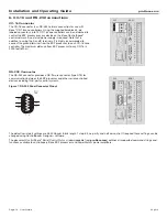
 

 CAUTION: 

Be sure all the fine strands of the wire are twisted together and contained within the connector. If even one strand is loose and can 

touch the adjacent terminal, a short circuit may occur.

The information furnished in this guide does not include all of the details of design, production, or variations of the equipment. Nor does it cover every 
possible situation which may arise during installation, operation, or maintenance. If you need assistance beyond the scope of this installation guide, 
please contact our Customer Service department. 

Summary of Contents for ESP-00 Series II

Page 1: ...ControlSpace Engineered Sound Processors Installation Guide ESP 00 Series II ...

Page 2: ......

Page 3: ...igner software 16 2 Unpacking 16 3 Expansion Card Installation 17 4 Rack Mounting 17 5 Analog Audio Connections using Option Cards 17 6 CC 16 and RS 232 connections 18 CC 16 Connector 18 RS 232 Connector 18 7 Connect GPIO Devices 19 General Purpose Inputs 19 General Purpose Outputs 19 8 Power Cord Connection and Switch 20 9 Network Connection 20 10 Configuration with ControlSpace Designer Software...

Page 4: ...d as the disconnect device such disconnect device shall remain readily operable See the additional instructions on the Important Safety Instructions sheet North America only enclosed in the shipping carton Provide an earth connection before the main plug is connected to the mains The lightning flash with arrowhead symbol within an equilateral triangle is intended to alert the user to the presence ...

Page 5: ...V 13 43A Inrush current after interruption for 5 sec 230V 13 09A Information about products that generate electrical noise If applicable this equipment has been tested and found to comply with the limits for a Class B digital device pursuant to Part 15 of the FCC rules These limits are designed to provide reasonable protection against harmful interference in a residential installation This equipme...

Page 6: ...omo dispositivo de desconexión deberá poder accionarse fácilmente Consulte las instrucciones adicionales de la hoja Instrucciones de seguridad importantes solo Norteamérica que se incluyen en el embalaje de envío Establezca una conexión de tierra antes de conectar el enchufe a la red eléctrica El símbolo de relámpago con una flecha dentro de un triángulo equilátero indica al usuario que la caja de...

Page 7: ...riente de irrupción después de interrupción durante 5 seg 230 V 13 09 A Información sobre productos que generan ruido eléctrico Se ha comprobado que este equipo cumple los límites para dispositivos digitales de clase B de acuerdo con el apartado 15 de las normas de la FCC Estos límites están diseñados para ofrecer una protección razonable contra las interferencias perjudiciales en una instalación ...

Page 8: ...rité Amérique du Nord uniquement joint au carton d expédition Avant de brancher l appareil à ne prise électrique vérifiez que celle ci est bien raccordée à la terre Le symbole représentant un éclair avec une flèche à l intérieur d un triangle équilatéral est utilisé pour prévenir l utilisateur de la présence d une tension électrique dangereuse non isolée à l intérieur de l appareil Cette tension e...

Page 9: ...rruption de 5 secondes 230 V 13 09 A Informations sur les produits générateurs de bruit électrique Ce matériel a fait l objet de tests prouvant sa conformité aux limites imposées aux appareils numériques de classe B conformément à la partie 15 des règlements de la FCC Ces limites sont conçues pour offrir une protection raisonnable contre les interférences nuisibles dans une installation résidentie...

Page 10: ...Sie den Netzstecker oder eine Mehrfachsteckdose verwenden um das Gerät von der Stromversorgung zu trennen sollten Sie sicherstellen dass Sie jederzeit auf den Stecker zugreifen können Weitere wichtige Sicherheitshinweise nur für Nordamerika finden Sie auf einem Hinweisblatt im Versandkarton Stellen Sie eine Erdung her bevor Sie den Netzstecker an eine Steckdose anschließen Das Blitzsymbol mit Pfei...

Page 11: ...tlinien erfüllt Die vollständige Konformitätserklärung ist einsehbar unter www Bose com compliance Dieses Produkt erfüllt die Anforderungen an die Störfestigkeit der Klasse E2 der Richtlinie EN55103 2 Einschaltstrom bei Kaltstart 230 V 13 43 A Einschaltstrom nach 5 Sekunden langer Unterbrechung 230 V 13 09 A Informationen über Produkte die elektrische Störgeräusche erzeugen Falls zutreffend wurde ...

Page 12: ...proForum Bose com Register and participate in forum user groups to post questions interface with Bose staff and share application information on this product Product Features Flexible I O through a customizable card frame design With a powerful DSP core the ESP 00 II processer accommodates up to 64 channels of audio over 8 open card slots and general purpose I O GPIO expansion up to 16 control inp...

Page 13: ...rder accessory cards as needed for your application At time of print the following expansion cards are available For further information on these cards and to view new cards that are available please visit pro Bose com where an online interactive configurator tool provides technical details assistance in populating expansion cards and additional information about user controls Dante network card P...

Page 14: ...rfaces can be used with the ESP 00 II engineered sound processor Figure 2 CC 64 Control Center 12 ControlSpace CC 64 control center PC 041760 Figure 2 Network control of any Bose networkable hardware ControlSpace CC 16 zone controller PC 041761 Uses CC 16 port Up to 15 devices can be used with any ESP engineered sound processor ControlSpace CC 4 room controller PC 042023 Uses GPI port Requires 5 c...

Page 15: ...cards 2 Card slot panels Removable panels houses up to eight expansion cards 3 CC 16 connector Allows Bose CC 16 zone controller connections See CC 16 Connector on page 18 4 GPIO slot 1 Pre loaded GPIO card which provides eight general purpose control inputs and eight general purpose control outputs See Connect GPIO Devices on page 19 5 GPIO slot 2 For optional 2nd GPIO card 6 Chassis serial numbe...

Page 16: ...nstall the latest version of ControlSpace Designer software 2 Unbox the ESP processor 3 Install expansion cards 4 Rack mount the ESP processor 5 Make audio I O connections 6 Make CC 16 and RS 232 connections 7 Connect GPIO devices 8 Establish a network connection 9 Connect the power cable turn on unit 10 Configure the ESP processor using ControlSpace Designer software 1 Download and install the la...

Page 17: ... in height and requiring a mounting depth of 13 1 inches 334 mm from the front rack rail Use four fasteners with washers not supplied to mount the unit The product uses side ventilation with air intake occurring on the right side and exhaust on the left side where a single fan is located Refer to page 22 for power dissipation ratings 5 Analog Audio Connections using Option Cards Using Euroblock co...

Page 18: ...ocessor to each CC 16 zone controller The maximum distance from ESP processor to any CC 16 is 2000 feet 610 m RS 232 Connector The RS 232 connector provides a DB 9 male connector type DTE for communication between the ESP processor and other serial controlled devices including third party control systems Figure 7 RS 232 Panel Connector Pinout The default serial port settings are 38 400 baud 8 bits...

Page 19: ...ving external devices Using Switches Both toggle switches and pushbuttons can be used with control inputs Each input terminal is tied to an internal pull up resistor 5k ohm so that external switches can be wired directly from input to ground Using Potentiometers 10k ohm potentiometers can be connected and associated with control gain blocks in a system design Inputs are compatible through software...

Page 20: ...wer consumption is less than 35VA and maximum power consumption is less than 70VA at less than 95ºF 35ºC ambient The power switch is located on the rear panel adjacent to the power cord inlet 10 Configuration with ControlSpace Designer Software With a network connection in place and ControlSpace Designer software installed use the Update Firmware tool inside ControlSpace Designer software to scan ...

Page 21: ...use the Designer software to reduce the input gain Verify that the audio output signal indicators are not solid red or flashing red If they are and the input indicators are green use the Designer software to reduce the output gain or any intermediary gain in the signal path If the input source signal is clean when it enters the ESP system and the input and output indicators are green verify that t...

Page 22: ...9 pin Output Voltage High 5 V 0 5 mA Low 1 V 10 mA open collector Indicators and Controls LED Status Indicators Power Status Ethernet Serial RS 232 CC 16 Audio Signal Indication Green 60 to 21 dBFS Yellow 20 to 7 dBFS Red 6 dBFS to Clip Electrical Specifications Mains Voltage 85 VAC 264 VAC 50 60 Hz with PFC AC Power Consumption 35 VA typical 70 VA max at 95 F 35 C ambient Mains Connector IEC 6032...

Page 23: ...anghai P R C 200041 China 86 21 6271 3800 France Bose S A S 12 rue de Temara 78100 St Germain en Laye France 01 30616363 Germany Bose GmbH Max Planck Strasse 36D 61381 Friedrichsdorf Deutschland 06172 7104 0 Hong Kong Bose Limited Suites 2101 2105 Tower One Times Square 1 Matheson Street Causeway Bay Hong Kong 852 2123 9000 India Bose Corporation India Private Limited 4th Floor Shriram Bhartiya Ka...

Page 24: ... 2013 Bose Corporation All rights reserved The Mountain Framingham MA 01701 9168 USA www pro Bose com All trademarks are the property of their respective owners AM372645 Rev 00 ...

Reviews: