Clip position
Back cover
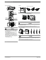
Flat head screwdriver
Front cover
Fig.5
Screw hole for
wall mounting,
use three GB950-
86 M4X20
Screw hole to install
onto 86 Electrician
box, use two M4X25
GB823-88
Screw hole for
wall mounting,
use one GB950-86
M4X20
Fig.6
Fig.7.1
Fig.7.2
Communication
cables
Back cover
86 Electrician box
CAUTION
1. To detach the controller, insert a flat head screwdriver
into the allocated slots at the bottom of the controller to
release the clips. (Fig.5)
2. Use three GB950-86 M4X20 screws to directly install
the wall mounting bracket to the wall. (Fig.6)
3. Use two M4X25 GB823-88screws to install the wall
mounting bracket to the 86 electrician box, and use one
GB950-86 M4X20 screws for fixing to the wall. (Fig.7.1)
4. Ensure when tightening the screws, that the controller is
flat against the wall. Make sure you don’t overtighten. This
may cause damage. (Fig.7.2)
5. Do not overt tighten the screws.
4.Back cover installation
5.Wiring
Top left wire outlet
Top wire
outlet
Left side
wire outlet
A.Wiring, three outlet positions
Knockout
Knockout
Knockout
Fig.8
B.Shielded wiring
86 Electrician box
Embedded 86 electrician box wiring
Wiring through the wall
Wall hole and wiring hole
Diameter:
Ø
8 ~
Ø
10
Fig.9
CAUTION
Keep away from the water. (Fig.10)
When installing, ensure you leave enough cable, for taking the controller off the wall.
6.Front cover installation
Fig.11
Fig.12
CAUTION
Fix the controller back into the wall bracket being careful not to trap the communication cable.
(Fig.11)
Ensure the controller is correctly fastened onto the wall. (Fig. 12)
4 | INSTALLATION PROCEDURE
6720863624 (2016/04)
CLIMATE 5000 VRF

