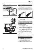
Installation
GREENSTAR WIRING CENTRE – 6720880441 (2018/01)
7
3.2.2
Mains voltage, pump and valve connection
(mains voltage side)
The allocation of the electrical connections depends on the system
installed. The description in Fig. 11 to Fig. 19 is a possible suggestion
for the electrical connection. Some steps are not shown in black. This
makes it easier to recognise which steps belong together.
DANGER:
Danger to life due to current!
If the heating system is wired so that the Greenstar Wiring Centre and
boiler have separate isolating devices (
▶ Attach a warning label to each point of isolation. This label has to
advise that it is not the sole point of isolation and it has to identify the
location of the other means of isolation.
▶ Electrically isolate the boiler and system components. Secure against
unintentional reconnection and make sure the power supply is
disconnected.
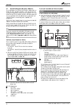
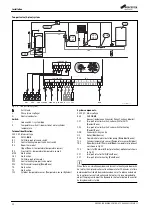
Fig. 10 Separate isolating devices
[1]
Fused spur
[2]
Greenstar Wiring Centre
[3]
Greenstar boiler
1)
The maximum power consumption of the connected components and
assemblies must not exceed the output stated in the module
specifications (
chapter 2.3, page 4).
▶ As the power supply is not provided via the electronic circuitry of the
heat source, install a circuit breaker complying to the applicable
standards to interrupt all phases of the power supply
(acc. to EN 60335-1).
The module cover needs to be removed to carry out the electrical
connections.
▶ Only use electric cable of similar quality.
▶ Ensure that the power supply is connected to the live, neutral and
earth terminals.
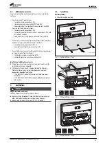
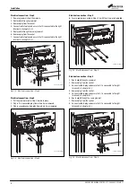
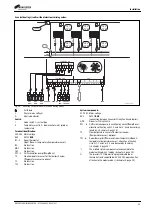
Electrical connection – Step 1
1. Remove grommets from the module.
2. Route cable through a grommet.
3. Remove plug from the socket.
4. Connect cable to plug and ensure that it is connected to the right
terminals (
chapter 3.3).
5. Route cable through the same grommet.
6. Remove plug from the socket.
7. Connect cable to plug and ensure that it is connected to the right
terminals (
chapter 3.3).
Fig. 11 Electrical connection – Step 1
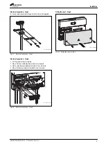
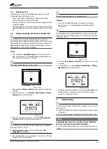
Electrical connection – Step 2
1. Put the grommet used in Step 1 back into place.
2. Plug in first connected plug from where it was removed.
3. Plug in second connected plug from where it was removed.
Fig. 12 Electrical connection – Step 2
1) Refer to the installation, commissioning and service instructions for the
compatible Greenstar boiler for specific boiler wiring connections.
. . . . .
N L
120/230VAC
L
N
1
2
BUS
1
2
BUS
N L
120/230VAC
. . . . .
L
N
0010016321-001
2
3
1
1
2.
1.
5.
5.
7.
7.
6.
6.
≥ 20 mm
3.
4.
0 010 013 190-001
1.
2.
3.
0 010 013 191-001

