


UHI/UHO Series
UHO-HBPS-10, -50, and UHO-HPS-50 | en
71
Bosch Security Systems, Inc.
Installation Manual
F.01U.167.418 | 3.0 | 2010.04
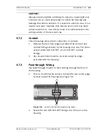
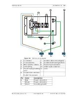
5.13
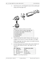
Fuse replacement
1.
To replace a fuse, pull the top of the fuse holder.
2.
Replace the fuse with a fuse that has the same current
rating. The fuse is a 5 mm x 20 mm slow blow breaking
capacity cartridge-type fuse.
There is a spare fuse inside the housing.
6
UHO-HBPS-10, -50, and UHO-HPS-50
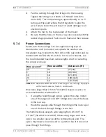
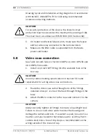
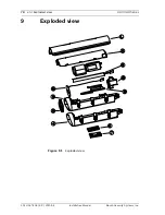
6.1
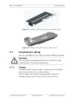
Camera/lens wiring
Installation for these models is in accordance with
Section 5 Installation
, except as noted below.
All electrical power connections are made through the 4-pin
connector. Cable Requirements for the 4-pin connector:
6.0 mm (0.24 in) to 12.0 mm (0.47 in)
1.
Cut the power cord on 230 VAC camera models, leaving
enough cable for connection to the terminal block. Strip no
less than 6 mm (0.25 in) and no more than 8 mm (0.31 in)
of insulation away from the wire. Be sure not to nick the
wires.
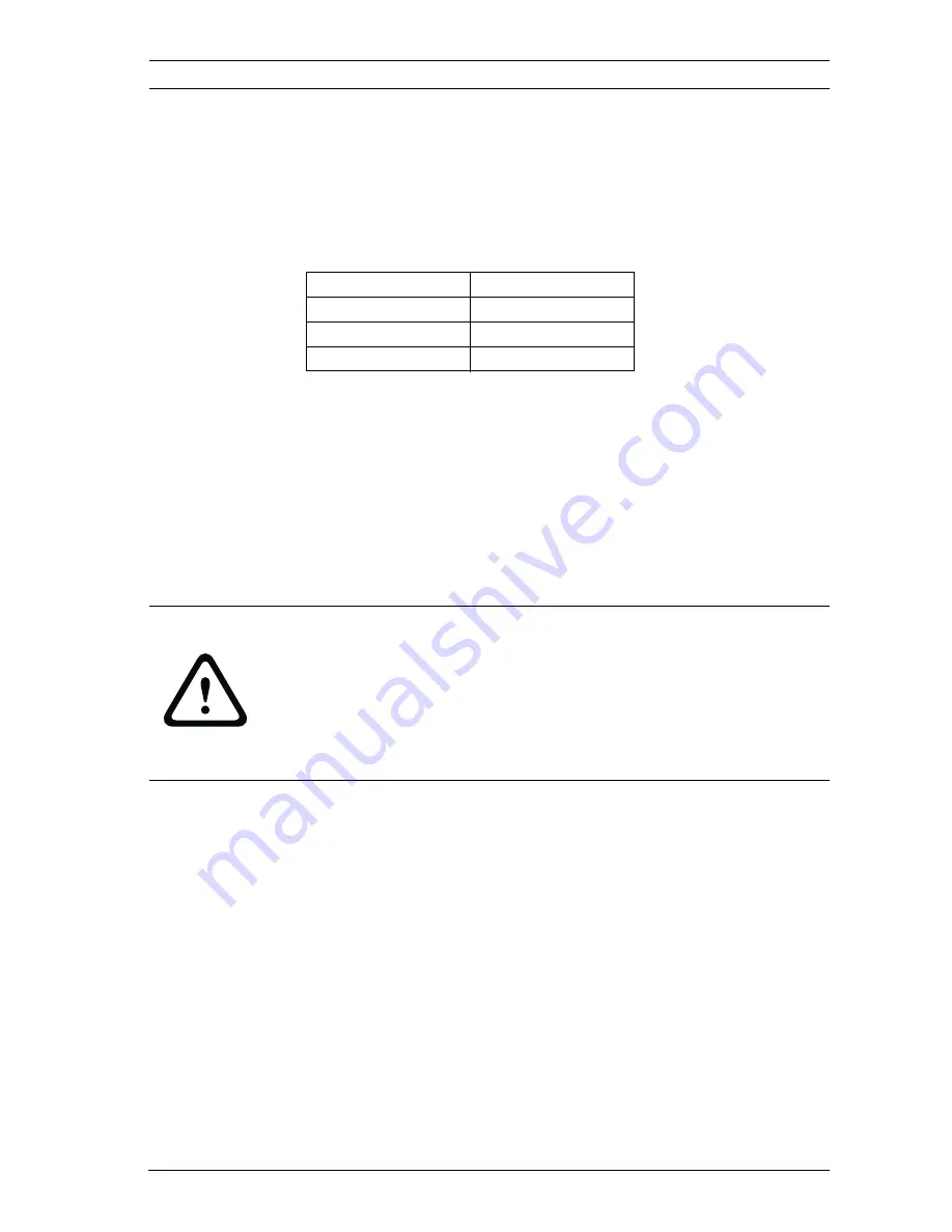
Camera voltage
Fuse rating
24 VAC
4 A, 250 VAC
120 VAC
2 A, 250 VAC
230 VAC
2 A, 250 VAC
CAUTION!
Use only 24 VAC power for UHO-HBPS-10 models. These
models have female connectors to prevent them from being
connected to the mating connector that is provided with UHO-
HPS-50 and UHO-HBPS-50 models that require 230 VAC. Ensure
that 230 VAC is not applied to the male mating connector.
Summary of Contents for UHI Series
Page 2: ......
Page 327: ......
Page 328: ...Bosch Security Systems Inc www boschsecurity com Bosch Security Systems Inc 2010 ...


