background image

Solution 6000

16

Bosch Security Systems   12/14   BLCC610U

User Guide

Access > User Properties >

Door Assignment

MENU  1-4-5

This menu allows you to assign each user to one or more 

door groups.  A door assignment is used to allow and/or 

restrict which users have access to various system outputs. 

These outputs can be used to control door strikes, gates or 

roller doors etc. 
Enter programming mode (PIN + MENU) then,

1.  Enter [MENU] + [1] + [4] + [5] and select the user 

from the list then press [OK].

Ur1 John Smith

Ur2 Debbie Smith

Ur3 User 3 Name

Press 



 OK or MENU

2.  Use the up and down arrow keys to highlight the 

door group then press the [ON] key to select or the 

[OFF] key to deselect.

  Door 1 Name

  Door 2 Name

  Door 3 Name

Press 



 OK ON OFF MENU

3.  Repeat Step 2 until all required door groups are 

programmed, then press [OK] to save and exit or 

press [MENU] to exit without saving.

Access > User Properties >

User Expire Date

MENU  1-4-6

This menu allows you to assign one or more users to expire 

on a date in the future.  This could be used when giving a 

code to a tennant in a holday house etc. Once the expire 

date is reached then all of the users credentials will cease 

working and they will no longer be able to access the 

system. 
Enter programming mode (PIN + MENU) then,

1.  Enter [MENU] + [1] + [4] + [6] and select the user 

from the list then press [OK].

Ur1 John Smith

Ur2 Debbie Smith

Ur3 User 3 Name

Press 



 OK or MENU

2.  Use the [

] and [

] keys to program the month, day 

and year.  Use [

] and [

] keys to scroll cursor left 

and right to between the month, day and year fields.

User Expire Date Ur1

Expire Date

01 Jan 2100

Press 



 OK to SAVE

3.  Press [OK] to save and exit, or press [MENU] to exit 

without saving.

Fingerprints

The addition of the optional fingerprint reader to your 

system allows you to  turn areas on and off or to open a door 

simply by presenting your fingerprint to the reader.  The 

following steps we help you to get the best performance 

from your fingerprint reader. 
1) When adding or enrolling fingerprints it is is important 

to place and hold you finger in the correct position while 

the system records the credential.  Your finger should be 

placed so that the pad is making full contact with the 

sensor.  Do not use your fingertip.

2) Always try to present your finger in the same posistion as 

you did when it was enrolled.  Use the raised dimple on the 

reader surface as a guide.  People with smaller fingers may 

find this dificult at first but with practice even they will be 

able to use the reader.

3) The reader will vibrate as soon as it has completed 

reading your fingerprint.  Once you feel the vibrations you 

should remove your finger.

4) If the reader fails on the first attempt, remove your finger 

and wait for the large blue guide indicator to come on 

before trying again.  Whenever the reader is busy working 

you may see the following screen on the keypad.  Wait for a 

few seconds before trying again.

Fr9 Unit Busy. Please try 

later.

Press OK or MENU

5) In some cases the unit may not be able to read a finger 

because the finger is cut or damaged by other means.  

Extremely wet or dry fingers may also cause read errors but 

these are rare.  In this case you should revert to using your 

PIN number on the standard keypad.

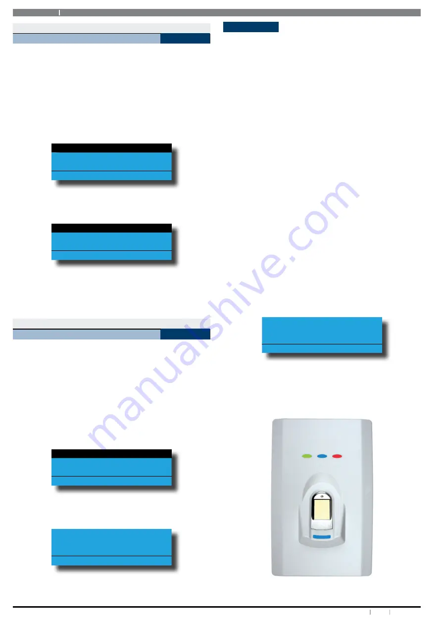
Figure 3: CM729B Fingerprint Reader

Summary of Contents for SOLUTION 6000

Page 1: ...Solution 6000 Security System User Guide EN Security Systems ...

Page 2: ...levelfromthisdeviceissetasafixedlevelandbecause of this there may be circumstances where the performance is less than optimal Before reporting such occurrences as faults please check the line with a standard telepermitted telephone Warnings 1 This product must be installed by a qualified and licensed security installer 2 This product may not perform as expected if installed incorrectly 3 Some feat...

Page 3: ...l Areas Off 18 Move To Area 18 Chime On Off 19 Chime Mode 19 Area Name 19 Part Mode 1 Name 20 Part Mode 2 Name 20 Auto Arming 20 Exit Time 21 Entry Time 1 21 Entry Time 2 21 Part Entry Time 22 Inputs 22 Zone Status 22 Zone Array 22 Bypass Zones 23 Set Chime Zones 23 Set Part 2 Zones 24 Smoke Sensor Reset 24 Zone Name 24 Walk Test All Zones 25 Walk Test A Single Zone 25 Outputs 25 Output Status 25 ...

Page 4: ...Solution 6000 4 Bosch Security Systems 12 14 BLCC610U User Guide Keypad Hi Lo Temp 41 Site Name 41 Walk Test All Zones 41 Battery Test 42 Installation Details 43 ...

Page 5: ...alk Test All Zones 4 2 0 Door Name 1 2 3 Edit Token 2 1 8 Auto Arming 3 9 1 Walk Test A Zone 4 9 Output Testing 1 3 RF Keyfob 2 8 Timers 4 9 0 External Siren Test 1 3 0 Add Keyfob 2 8 0 Exit Time 4 9 1 Internal Siren Test 1 3 1 Delete Keyfob 2 8 1 Entry Time 1 4 9 2 Strobe Test 2 8 2 Entry Time 2 4 9 3 Fire Siren Test 1 4 User Properties 2 8 3 Part Entry Time 1 4 0 User Name 1 4 1 Area Assignment ...

Page 6: ... hard for someone else to guess For security reasons do not write this PIN down or give it to anyone else If more than one person needs to operate the system then you should create a different PIN code for them if this has not been done by your installer This guide will explain how to do this See MENU 1 1 2 on page 12 Please take the time to familiarise yourself with the following terms before rea...

Page 7: ... turn an area or output on If your system has been partitioned press and hold the ON key for two seconds to turn all areas on at the same time Key Description The PART key allows you to turn an area Part On This key can also be used to bypass a zone or multiple zones when you press and hold for two seconds The OFF key allows you to turn an area or output off If your system has been partitioned pre...

Page 8: ... is active Off User Programming Mode is Active Blue LED On Door Locked Fast Flash Door Unlocked 2 Flashes Door Unlocked by TimeZone Off Access Group not programmed Table 3 Status ICONs LED Indicator s and Their Meanings Keypad Tones Your keypad emits several distinct tones and displays text to alert you to system events Additional bells or sirens may also be connected to your system Bells or siren...

Page 9: ...Part On A master user can program which zones are monitored when a user turns an area Part 2 On Once you have turned an area Part On or Part 2 On exit delay time starts to count down You should leave all zones that are active before exit delay time expires Leaving active zones after exit delay expires causes an alarm event Use Part On or Part 2 On only when you want part of an area turned on 1 Mak...

Page 10: ...accending frequency if the panel is in the disarmed condition Press 0 to arm You will hear 3 beeps in decending order when the panel arms All areas on the system will be armed regardless of there condition when using the DTMF quick arm function DTMF Control Functions Your system includes comprehensive DTMF control of individual areas and outputs with full user PIN and timezone access verification ...

Page 11: ...gh entire character list Scroll Down through entire character list Move to left one character position Move to right one character position OFF Clear from cursor postiion to end of line Table 6 Text Keypad Character Set Once the desired character is displayed press the right arrow key to move to the next character position To save programming changes press OK or press MENU to exit without saving T...

Page 12: ... new PIN must have the same number of digits as the old PIN At factory default each PIN is fixed to 4 digits in length The default PIN for User 1 Master user is 2580 Enter programming mode PIN MENU then Ensure that the system or area is turned off 1 Press MENU 1 1 1 The keypad will display a list of available users that you can change their PIN Ur1 John Smith Ur2 Debbie Smith Ur3 User 3 Name Press...

Page 13: ...nu allows a Master user the ability to add a new token for those users that have been assigned to the same area s as the Master user Enter programming mode PIN MENU then 1 Enter MENU 1 2 0 A list of users will display on the keypad 2 Use the and keys to select the user that you want to add a token for then press OK to select Ur1 John Smith Ur2 Debbie Smith Ur3 User 3 Name Press OK or MENU 3 If you...

Page 14: ... add the RF keyfob ID then press OK to select Alternatively you can enter the user number you then press OK The keypad will prompt you to enter the RF keyfob ID number Enter Keyfob ID Ur16 User 16 Name 000000000 Press OK or MENU 3 Enter the RF Keyfob ID Number 4 Press OK to save and exit or press MENU to exit without saving Access RF Keyfob Delete Keyfob MENU 1 3 1 This menu allows the security in...

Page 15: ...s MENU 1 4 2 This menu allows the master user to set or change various options for other users on the system You should discuss these options with your installer before making changes Follow the procedure below to configure the required options 1 Enter your Master PIN MENU 2 Enter 1 4 2 OK The keypad will display the list of current options Options with a preceeding tick mark are selected Master U...

Page 16: ...and year fields User Expire Date Ur1 Expire Date 01 Jan 2100 Press OK to SAVE 3 Press OK to save and exit or press MENU to exit without saving Fingerprints The addition of the optional fingerprint reader to your systemallowsyouto turnareasonandoffortoopenadoor simply by presenting your fingerprint to the reader The following steps we help you to get the best performance from your fingerprint reade...

Page 17: ...s as the Master user Enter programming mode PIN MENU then 1 Enter MENU 1 8 1 A list of users will display on the keypad 2 Use the and keys to select the user who s fingerprint you want to delete then press OK to select Ur1 John Smith Ur2 Debbie Smith Ur3 User 3 Name Press OK or MENU The keypad will display Press OK to delete Fingerprint for Ur1 User 1 Name Press OK or MENU 3 When prompted press th...

Page 18: ...OK to select Alternatively you can enter the area number you want to turn on or off then press OK Areas Commands Turn All Areas On MENU 2 0 2 This menu allows you to turn on all areas that your PIN has been assigned to at the same time All On The keypad display below shows the area icons 1 through to 8 Enter programming mode PIN MENU then 1 Enter MENU 2 0 2 The keypad will display the exit time ba...

Page 19: ...urned on Reception Area A1 Chime is ON To turn OFF Press OFF To Go Back Press OK 3 Press the ON key to turn chime mode on or press OFF to turn chime mode off 4 Press the OK key to exit i Note Holdingdownthe4keyonthekeypadfor2seconds will also turn chime mode on and off Areas Commands Chime Mode MENU 2 0 6 This menu allows you to program how the chime alert behaves when a chime zone is triggered Th...

Page 20: ...nter MENU 2 1 7 A list of different areas will display on the keypad 2 Use the and keys to select the area that you want to program the part mode 2 name for then press OK to select Alternatively you can enter the area number that you want to program the name then press OK The keypad will display the following Part Mode 2 Name A1 Part 2 Area 1 Name Press OK to SAVE 3 Use the and keys to scroll the ...

Page 21: ...e 1 or entry time 2 The entry time is the amount of time you have to turn your alarm system off once the entry zone have been triggered or opened The keypad will sound an entry warning beep during this time to let you and other users know that the area needs to be disarmed If the area is not disarmed before the entry time expires then an alarm will occur Enter programming mode PIN MENU then 1 Ente...

Page 22: ...er programming mode PIN MENU then 1 Enter MENU 2 8 3 A list of available areas will display on the keypad A1 Reception Area A2 Sales Dept A3 Administration Dept Press OK or MENU 2 Use the and keys to select the area that you want to program the entry time for then press OK to select Alternatively you can enter the area number that you want to program then press OK The keypad will display the follo...

Page 23: ...ENU 3 0 2 A list of zones that can be bypassed will display on the keypad A displayed on the right side of the zone name indicates that the zone is already bypassed Zn1 Zone 1 Name Zn2 Zone 2 Name Zn3 Zone 3 Name Press OK or MENU 2 Use the and keys to select the zone that you want to bypass then press OK Alternatively you can enter the zone number that you want to bypass then press OK If the zone ...

Page 24: ...to set for Part 2 then press OK Alternatively you can enter the zone number that you want to set for Part 2 then press OK If the zone is not programmed for Part 2 the keypad will prompt Zone 1 Name Zn1 Is not armed in Part2 To Enable Press ON To Go Back Press OK If the zone is programmed for Part 2 the keypad will prompt Zone 1 Name Zn1 Is armed in Part2 To remove Press OFF To Go Back Press OK 4 P...

Page 25: ...hout saving Inputs Input Testing Walk Test A Single Zone MENU 3 9 1 This menu allows you to select a single zone to be tested via walk test Enter programming mode PIN MENU then 1 Press MENU 3 9 1 The keypad will display a list of zones that are available to be tested via walk test 2 Use the and keys to select the zone that you want to walk test then press OK to select Alternatively you can enter t...

Page 26: ... OK To turn the output on press ON The keypad will display the following when the output is on External Siren Op1 Output is ON To turn OFF Press OFF To Go Back Press OK To turn the output off press OFF 4 Press OK to save and exit or press MENU to exit without saving Outputs Commands Output Array MENU 4 0 2 This menu allows master users to view the status of outputs on the system in groups of 16 Ou...

Page 27: ...r the third row displays the door status L Door Locked U Door Unlocked O Override Disabled or Not Available Enter programming mode PIN MENU then 1 Enter MENU 4 0 4 The keypad will display the following door array information for doors 1 to 16 0000000001111111 1234567890123456 LLLLL UUUUO Press OK or MENU In the above example screen L Doors 01 to 05 are Locked O Door 13 has a Override condition U D...

Page 28: ...r left and right across the door name text Use the and keys to scroll through the different characters available To clear all text from the cursor position to the right press the OFF key 4 Press OK to save and exit or press MENU to exit without saving Outputs Output Testing External Siren Test MENU 4 9 0 This menu allows you to test any external sirens which have been connected by your installer T...

Page 29: ... keypad will display a list of areas A1 Security System A2 Area 2 Name A3 Area 3 Name Press OK or MENU 2 Use the and keys to select the area that you want to test the fire sirens in then press OK Alternatively you can enter the area number then press OK The keypad will display the following during the fire siren test Fire Audible Testing Press any key to abort Press OK or MENU When the test is com...

Page 30: ...mming information is included with the voice module Comms Commands Register Customer MENU 5 0 8 Reserved for future use Comms Telephone Numbers Destination 1 MENU 5 1 1 The installer may have configured your system to report alarm messages using one of the self monitoring formats such as SMS Domestic or Voice reporting When one of these formats has been configured the system will send alarm report...

Page 31: ...f the self monitoring formats have been configured by your installer See MENU 5 1 1 for more information Enter programming mode PIN MENU then 1 Enter MENU 5 1 2 If the control panel is not programmed to report using one of the self monitoring formats the keypad will display the following Reporting format does not allow user changes Contact installer for further information If the control panel has...

Page 32: ...by scrolling the cursor left and right For special characters eg pause or etc use the and keys 3 Press OK to save and exit or press MENU to exit without saving Comms Remote Access User RAS PIN MENU 5 3 8 0 0 0 0 0 0 0 0 The RAS security PIN programmed here must match the security PIN programmed in the customer file of the Site Manager RAS upload download database otherwise a connection to the pane...

Page 33: ...nd Reports 4 Access Reports Send Reports 5 Reserved 6 Reserved 7 Reserved 8 Reserved Table 7 Email Options 1 Enter your Master PIN MENU 2 Enter 5 5 9 OK The keypad will display the list of current options Options with a preceeding tick mark are selected Open Close Zones System Press OK ON OFF MENU 3 Use the and keys to highlight the feature that you want to program then use the ON and OFF keys to ...

Page 34: ...ands Keypad Contrast MENU 6 0 8 This menu allows you to adjust the contrast of the keypad s LCD display Each keypad can have their display adjusted separately Enter programming mode PIN MENU then 1 Press MENU 6 0 8 The keypad will display the contrast screen L Keypad 001 Contrast Press SAVE OK to H 2 Use the and keys to adjust the bar until the desired contrast is reached 3 Press OK to save and ex...

Page 35: ...following Trigger Table 1 Phone 1 61423474345 Press 0 9 OK to SAVE 4 Use the and keys to scroll the cursor left and right across the phone number Use the and keys to change the individual digit in the number or press the OFF key to clear the whole number and then enter the new number using the 0 9 keys 5 Press OK to save and exit or press MENU to exit without saving i Note Your phone must be set t...

Page 36: ...ble MENU 7 0 1 The System Trouble Menu displays all current system troubles in a list format Some trouble events require you to drill down to fully interpret while others such as an unsealled zone can be interpreted at the top level Table 8 Control Panel Trouble Messages on page 37 lists the various trouble conditions that may be displayed and their meanings Enter programming mode PIN MENU then 1 ...

Page 37: ...ompany Sensor Watch Alert The control panel has detected a zone has failed to detect a change of state within the sensor watch period set by the installer Comms BUSS Trble The system has failed to communicate to a system device e g keypad etc Default PIN Trble The system has detected that either the Installer PIN or User 1 PIN has not been changed from the factory default codes These codes should ...

Page 38: ...s OK or MENU to exit Some other examples of event in the history log are as follows 1 E202 Sun 01Apr 03 41 45 Disarmed by User Area 1 Name Ur1 User 1 Name E202 Dest SLL Kp1 Keypad 1 Name Panel 1 Dest 1 at 01 Apr 03 41 57 2 E405 Sun 01Apr 06 41 45 Burglary Zone Bypassed Area 1 Name Zn3 Zone 3 Name E405 Dest SLL Ur1 User 1 Name Panel 1 Dest 1 at 01 Apr 06 41 57 The Dest field displays the various re...

Page 39: ...user from accessing the system at certain times of the day or days of the week The following options allow you to vary or change the times at which the timezone operates There are up to 16 different timezones available on the system and each one can have up to 4 separate start and stop times if required Your installer will advise you on the exact configuration and function of the timezones in your...

Page 40: ...one that you want to change then press OK to select The keypad will display the following Day Tz2 Period 1 S M T W T F S Hol N N N N N N N N Press 1 8 OK to SAVE 4 Press 1 to 8 to enable disable the days of the week that the timezone will operate 5 Press OK to save and exit or press MENU to exit without saving System TimeZones TimeZone Options MENU 7 5 3 Thismenuallowsthemasterusertoselectvarioust...

Page 41: ...emp 000 000 Press OK to SAVE 2 Use the and keys to program the High and Low temperatures To toggle between the High and Low temperature use the and keys Range 0 C to 50 C 3 Press OK to save and exit or press MENU to exit without saving System System Testing Site Name MENU 7 7 7 This menu allows the master user to program or modify the site name The site name can be used to name the entire system r...

Page 42: ...Testing Battery Test MENU 7 9 1 This menu allows you to manually test the systems back up battery The system will automatically test the battery every four hours and every time the system is armed The battery test can take up to two minutes to complete and the keypad will display the voltage of the battery during the test Enter programming mode PIN MENU then 1 Press MENU 7 9 1 The keypad will disp...

Page 43: ...43 Bosch Security Systems 12 14 BLCC610U Solution 6000 User Guide Installation Details INSTALLED BY DATE PHONE FAX EMAIL SERVICE PHONE FAX EMAIL MONITORED BY PHONE FAX EMAIL WARRANTY EXPIRES NOTES ...

Page 44: ...tination 1 Telephone Numbers 30 Destination 2 Telephone Numbers 31 Direct Connect 30 Email Address 32 Email Options 33 Email System Log 30 Register Customer 30 Send Test Report 33 User RAS PIN 32 Voice Setup 30 D Device Status 34 Doors Door Array 27 Door Assignment 16 Door Status 27 DTMF Operations 10 Duress Alarm 11 E Email Address 32 Email Options 33 Emergency Alarms Keypad Alarm Triggers 8 F Fe...

Page 45: ... 38 Holidays 40 Panel Status 36 TimeZones 39 Trouble 36 T Telephone Numbers Call Forward Off 32 Call Forward On 31 Destination 1 30 Destination 2 31 Testing Battery Test 42 Walk Test All Zones 41 Test Report Send Test Report 33 TimeZones Array 38 Name 39 Options 40 Set Days 40 Set Start Stop Times 39 User Access 15 Tokens Add 13 Delete 13 Edit 14 Status 13 Trouble 36 U User RAS PIN 32 Users Area A...

Page 46: ...Solution 6000 46 Bosch Security Systems 12 14 BLCC610U User Guide ...

Page 47: ...47 Bosch Security Systems 12 14 BLCC610U Solution 6000 User Guide ...

Page 48: ...Bosch Security Systems 25 Huntingwood Drive Huntingwood NSW 2128 Australia Phone 612 9672 1777 Facsimile 612 9672 1717 2014 Bosch Security Systems BLCC610U Issue FTR1 1 ...

Reviews: