


1. Assemble pump hub onto the pump shaft
If provided, insert the distance sleeve 6.1 onto the shaft of the pump.
Insert the pump hub 3.1 onto the shaft of the pump by considering the
adjustment dimensions and fasten the hub with the clamping screw
3.5a.
2. Assemble the motor hub onto the motor shaft
If provided, insert the distance sleeve 6.2 onto the shaft of the motor.
Insert the motor hub 3.3 onto the shaft of the motor by considering the
adjustment dimensions and fasten the hub with the clamping screw 3.4.
3. Screw on pump on bellhousing
Fasten the pump 1 with screws 1.2 and washers 1.1 onto the bellhous‐
ing 2. The leakage hole within the bellhousing must show down in the
case of horizontal assembly.
4. Screw on motor on bellhousing.
Fasten the motor 5 with screws 5.1 onto the bellhousing 2. When joining
the coupling heed the correct seat of the ring gear 3.2.
In the case of fastening A and B acc. to the type code, the leakage hole
must be at the bottom that escaping oil can flow out.
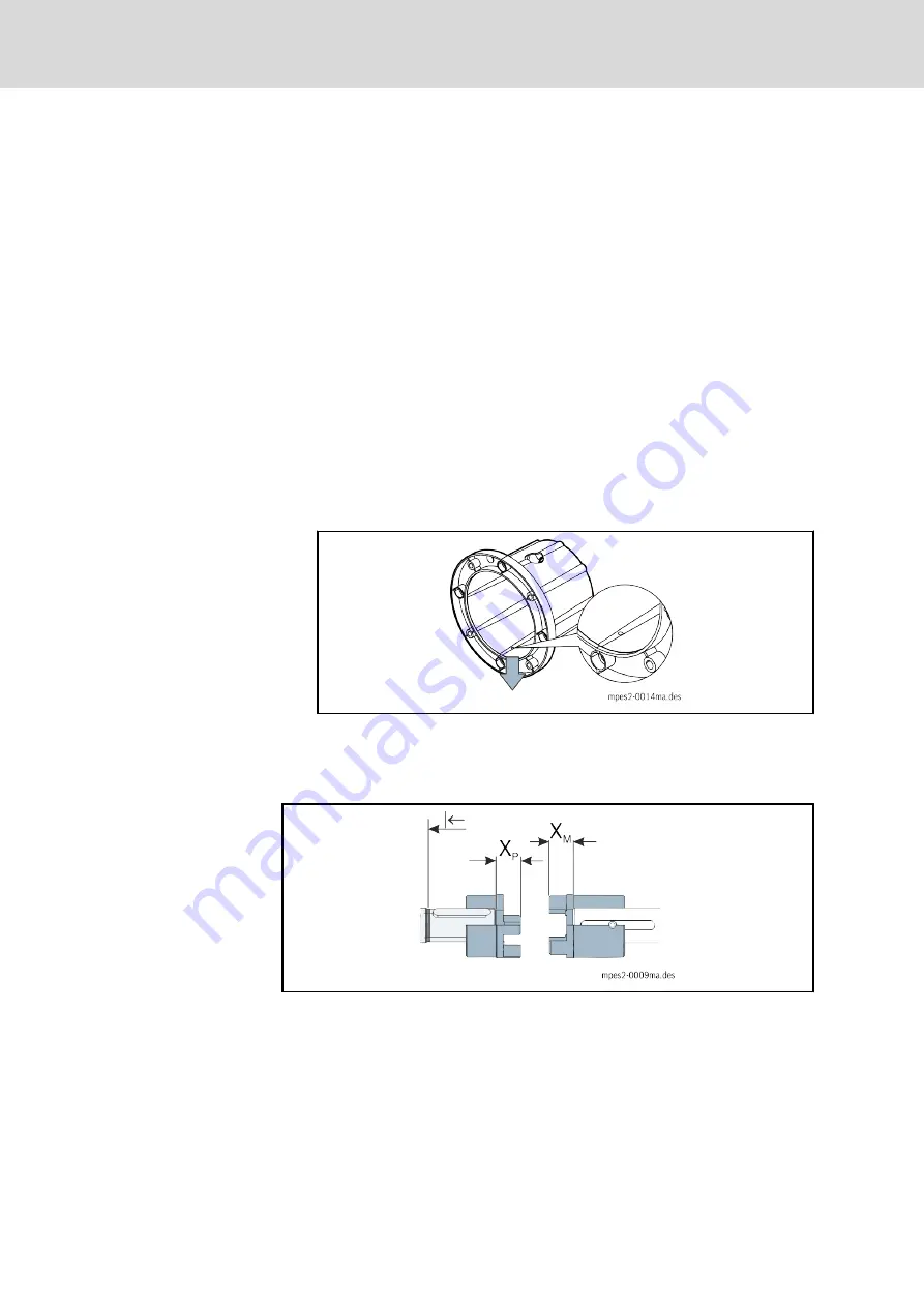
Fig. 7-10:
Leakage hole
5. Screw on pump foot
Fasten the optional pump foot 4 with the screws 4.1, washers 4.2 and
hexagon nuts 4.3 on the motor-pump unit.
X
P
Assembly dimension pump: front face o fhub to front face of
shaft pump
X
M
Assembly dimension motor hub: front face o fhub to front face
of shaft motor
|←
Assembly of hub as far as it will go
Fig. 7-11:
Assembly dimensions
Bosch Rexroth AG
DOK-SYTROX-MPES2******-IT01-EN-P
Rexroth Sytronix FcP 50xx/70xx Motor-Pump Unit MPES2
56/143
Mounting
LSA Control S.L. www.lsa-control.com [email protected] (+34) 960 62 43 01