50 / 74
MKE Synchronous Servomotors
Electrical connection
Bosch Rexroth AG
R911402016, Edition 02
Pos
Material number
Designation
Quantity
View
0500
R911400168
DOK-MOTOR*-MKE1XX*****-ISRS-D0-P
1
0510
R911278283
LOCKING CONNECTOR 2X5 POL.
1
3010
R911211410
TERMINAL END KQ-M3_/0.25-01.5RD16& 2
3030
R913018334
CYLINDER HEAD SCREW ISO4762-
M6X25-8.8-CM&
4
3040
R911286371
Connector housing 10pol. 87613-005
1
3050
R911260765
CONTACT KON-EF-0.32/0.52-NNN&
10
WARNING
Danger of explosion by using improper cable
glands.
−
The Ex cable glands and cables must be
evaluated, selected and assembled by the
machine builder and always in combination
with the cables used in accordance with DIN
EN 60079-14 "Potentially explosive atmos-
pheres - Planning, selection and installation
of electrical systems".
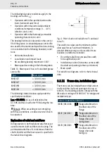
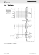
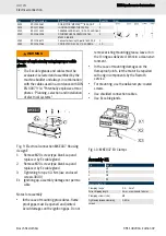
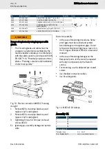
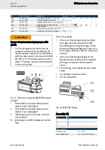
Fig. 21: Electrical connection MKE118 Housing
design E
1
Remove M25 screw-type blank cap and
replace it by Ex cable gland
2
Remove M20 screw-type blank cap and
replace it by Ex cable gland
3
Tightening torque 6.3 Nm (use enclosed
screws 3030)
Ex Ignition gap, assembly damage not permis-
sible
Notes for assembly
•
In the case of mounting procedures, flame-
proof gaps must be opened and jointed.
Avoid damages on the ignition gaps. Do not
remove existing mounting grease, leave it on
the O-rings as delivered. Work in a clean envi-
ronment.
•
In the case of mounting damages on the
flameproof joints, let the motor be repaired
with origin components by the Rexroth
service.
•
The lid screws are coated. For mounting, use
the delivered pre-coated screws. Clean the
screw-in threads before screwing in the
screws.
•
Use shielded connection cables.
•
Use Ex cable glands.
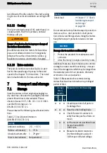
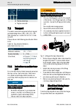
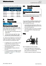
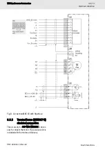
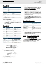
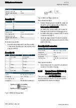
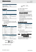
Fig. 22: MKE118 Clamps
Assembly -X1
Pin
Signal
1
U1
2
V1
3
W1
4
PE
Technical data -X1
Clamping range
0.5 … 10 mm
2
Wire stripping length
12 mm
Use wire end ferrules
Clamping screws (size)
M4

