background image

16 / 74

MKE Synchronous Servomotors

Important directions on use

Bosch Rexroth AG

R911402016, Edition 02

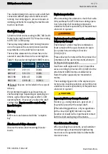
Meaning of symbols

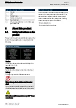
Table 3: Meaning of symbols

Symbol

Meaning

Reference to supplementary docu-

mentation

Explosion protection identification

The UL Recognized Component

Mark identifies recognized compo-

nent parts which are components

of a bigger product or system.
The letters “C” and “E” stand for

“Conformité Européenne”. The CE-

marking expresses the conformity

of a product with relevant EC-regu-

lations.

SI

Components for the use in systems

for “integrated safety technique”

prepared.
The symbol indicating "separate

collection" for all batteries and

accumulators is the crossed-out

wheeled bin.

Markup

The following markups are used for a user-

friendly text information representation:
Reference to supplementary documentation

Remark:


This note gives important informa-

tion, which must be observed.

Listings on the first level contain a bullet

point

Listings on the second level contain a

dash

Instruction

Instruction

🡆

Result of one instruction

Instruction multilevel

1.

Action step one

2.

Action step two

🡆

Result of an instruction

Please comply with the order of the handling

instructions.

2

Safety instructions

Observe the general safety notes in this chapter

and the safety instructions in this documentation.

Therewith, you avoid personal danger, damage

and errors.

Remark:


This operating instruction must be

stored and transferred in case of sale during the

complete product lifetime.

2.1

Important directions on

use

2.1.1

Intended use

Prerequisites for proper and safe use of the

motors are proper transport, appropriate

storage, proper assembly and connection,

careful maintenance, operation and overhaul.
The motors are suited for proper use in haz-

ardous areas according to ATEX Directive

2014/34/EU.
The motors have been designed for installation in

industrial machinery. The motors are according to

the following standards.

Standards

EN


IEC

60079-0

Potentially explosive areas – Part


0: Equip-

ment – General requirements

EN


60079-1 Explosive atmospheres - Part 1: Equipment

protection by flameproof enclosures “d”

EN


60079-31 Potentially explosive atmosphere – Part 31:

Equipment dust ignition protection by enclo-

sure “t”

The machine manufacturer must evaluate the

electric and mechanic safety as well as environ-

mental influences in the assembled state of the

Summary of Contents for Rexroth MKE

Page 1: ...MKE Synchronous Servomotors acc to ATEX Directive 2014 34 EU Operating Manual R911402016 Edition 02 ...

Page 2: ...rty rights Liability The specified data is intended for product description purposes only and shall not be deemed to be a guaranteed characteristic unless expressly stipulated in the contract All rights are reserved with respect to the content of this documentation and the availability of the product DOK MOTOR MKE GEN3 IT02 EN P DC AE EPI5 jw mb 1ad0017a7e013bc70a347e880be4fb79 2 en_US ...

Page 3: ... Maschinen und Maschinenteilen auf Verhindern Sie den unbeabsichtigten Zutritt für Personen Bringen Sie vor dem Zugriff oder Zutritt in den Gefahrenbereich die Antriebe sicher zum Still stand Dangerous movements Danger to life Keep free and clear of the ranges of motion of machines and moving machine parts Prevent personnel from accidentally entering the range of motion of machines Make sure that ...

Page 4: ... manipular los componentes de accionamiento Tenga en cuenta los tiempos de descarga de los condensadores Alta tensão elétrica Perigo de vida devido a choque elétrico Opere componentes de acionamento apenas com condutores de proteção instalados Desligue a alimentação de tensão antes de aceder aos componentes de acionamento Respeite os períodos de descarga dos conden sadores Alta tensione elettrica ...

Page 5: ...rmatie volledig gelezen begrepen en in acht genomen heeft Mocht u niet beschikken over documenten in uw landstaal kunt u contact opnemen met uw plaat selijke Rexroth distributiepartner Uitsluitend gekwalificeerd personeel mag aan de aandrijvingscomponenten werken Meer informatie over de veiligheidsinstructies vindt u in hoofdstuk 1 van deze documentatie Hög elektrisk spänning Livsfara genom elchoc...

Page 6: ...ieczeństwa Nie uruchamiać produktów przed uprzednim przeczytaniem i pełnym zrozumieniem wszyst kich dokumentów dostarczonych wraz z pro duktem oraz wskazówek bezpieczeństwa Należy przestrzegać wszystkich zawartych tam zaleceń W przypadku braku dokumentów w Państwa języku prosimy o skontaktowanie się z lokalnym partnerem handlowym Rexroth Przy zespołach napędowych może pracować wyłącznie wykwalifik...

Page 7: ...ii Nie wrzucać baterii do ognia Nesprávné zacházení s bater iemi Nebezpečí zranění Nepokoušejte se znovu aktivovat nebo dobíjet prázdné baterie nebezpečí výbuchu a pole ptání Nerozebírejte ani nepoškozujte baterie Nehá zejte baterie do ohně Slovensko Slovenčina Română Življenjska nevarnost pri neu poštevanju naslednjih napotkov za varnost Izdelke začnite uporabljati šele ko v celoti pre berete raz...

Page 8: ...o opremo Neodborná manipulácia pri transporte a montáži Nebezpečenstvo pora nenia Používajte vhodné montážne a transportné zar iadenia Používajte vhodné náradie a osobné ochranné prostriedky Manipulare necorespunzătoare la transport şi montaj Pericol de vătămare Utilizaţi dispozitive adecvate de montaj şi trans port Folosiţi instrumente corespunzătoare şi echipa ment personal de protecţie Nepravil...

Page 9: ...арати Достъпът за гореспоменатите лица до зони в които ще се монтират и ще работят задвижващи компоненти се забранява или разрешава само след консултация с лекар Elektromagnētiskais magnēt iskais lauks Veselības apdraudējums personām ar sirds stimulatoriem metāliskiem implantiem vai dzirdes aparātiem Tuvošanās zonām kurās tiek montēti un darbināti piedziņas komponenti iepriekš minētajām per sonām ...

Page 10: ...atekdami į pavojaus zoną saugiai išjun kite pavaras Ohtlikud liikumised Eluohtlik Ärge viibige masina ja masinaosade liikumispiir konnas Tõkestage inimeste ettekavatsematu sisenemine masina ja masinaosade liikumispiirkonda Tagage ajamite turvaline seiskamine enne ohu piirkonda juurdepääsu või sisenemist Επικίνδυνες τάσεις Κίνδυνος θανάτου Μην στέκεστε στην περιοχή κίνησης μηχανημάτων και εξαρτημάτ...

Page 11: ...ς μπαταριών Κίνδυνος τραυματισμού Μην επιδιώκετε να ενεργοποιήσετε ξανά ή να φορτίσετε κενές μπαταρίες κίνδυνος έκρηξης και διάβρωσης Μην διαλύετε ή καταστρέφετε τις μπαταρίες Μην απορρίπτετε τις μπαταρίες στη φωτιά 中文 如果不按照下述指定的安全说明使用 将会导致人身伤害 在没有阅读 理解随本产品附带的文件并熟知正当使用前 不要安装或使用本产品 如果没有您所在国家官方语言文件说明 请与 Rexroth 销售伙伴联系 只允许有资格人员对驱动器部件进行操作 安全说明的详细解释在本文档的第一章 高电压 电击导致生命危险 只有在安装了永久良好的设备接地导线后才可以对驱动器的部件进行操作...

Page 12: ... voltage 18 2 4 3 Protection from mechanical danger 18 2 4 4 Protection against magnetic and electromagnetic fields 18 2 4 5 Protection against ignitable electrostatic discharges 19 2 4 6 Protection against burns 19 2 4 7 Electrostatic sensitive devices ESD 19 3 Scope of delivery 20 4 Explosion protection 20 4 1 EU type test certificate number 20 4 2 Product description 20 4 3 ATEX labeling for MK...

Page 13: ...havior 35 6 2 10 Bearing 35 6 2 11 Frame size installation type 36 6 2 12 Coating 37 6 2 13 Noise emission 37 7 Transport and storage 37 7 1 Storage 37 7 2 Transport 38 7 2 1 Instructions on machine transport 38 7 3 Shock load during transport und storage 38 8 Assembly 39 8 1 Flange assembly 39 8 2 Assemble transmission elements 39 8 3 Electrical connection 40 8 3 1 Electrical connection general n...

Page 14: ...7 11 1 Tools required 57 11 2 Replace the motor 57 11 3 Preparing storage 57 12 Environmental protection and disposal 58 13 Eliminate malfunction 60 14 Technical data 60 14 1 Technical data type plate 60 14 2 Axial force 61 14 3 Radial force 61 14 3 1 MKE037 Radial force 61 14 3 2 MKE047 Radial force 61 14 3 3 MKE098 Radial force 62 14 3 4 MKE118 Radial force 62 14 4 Specifications 63 14 4 1 MKE03...

Page 15: ...en tion to the safety instructions and describes the seriousness of the danger The warning triangle with exclamation mark indicates the danger for persons DANGER Non compliance with this safety instructions will result in death or severe personal injury WARNING Non compliance with this safety instructions can result in death or severe personal injury CAUTION Non compliance with this safety instruc...

Page 16: ...step one 2 Action step two Result of an instruction Please comply with the order of the handling instructions 2 Safety instructions Observe the general safety notes in this chapter and the safety instructions in this documentation Therewith you avoid personal danger damage and errors Remark This operating instruction must be stored and transferred in case of sale during the complete product lifeti...

Page 17: ...ersonnel contains knowl edge and observance of the specifications in DIN EN 60079 14 All persons working on with or in the vicinity of an electrical system must be informed of the rele vant safety requirements safety guidelines and internal instructions EN 50110 1 2 3 General safety instruc tions Do not install or operate motors or components of the electric drive and control system before you hav...

Page 18: ...nts 2 4 3 Protection from mechanical danger Dangerous movements Danger to life risk of injury heavy injury or material damage Do not stay within the motion zone of the machine Avoid unauthorized access into the danger zone Additionally secure vertical axes to prevent them from sinking or descending after having shutdown the motor for instance as follows Mechanically lock the vertical axis providin...

Page 19: ...ust Electrostatic charges may be caused e g by the following processes electrostatic painting pneumatically conveyed dust or bulk material hydraulically conveyed or flowing liquids and droplets mechanically driven belts brushes and films etc Danger of explosion due to highly charge gener ating processes Highly charge generating processes may cause bush discharges or propagating bush discharges and...

Page 20: ... temperature class The housing is made of aluminum aluminum die casting Cooling is done via heat exchange of the open coolant circuit by temperature difference between housing and surrounding coolant air The motors can be fitted with a holding brake and with a Multiturn or Singleturn encoder MKE motors are supplied with dummy plugs without sealings The electrical connection is made via connecting ...

Page 21: ... opera tion or foreseeable failures malfunctions 4 5 Specific conditions WARNING Explosion hazard and danger to life or substan tial property damage All used components and accessory parts must fulfill the requirements for explosion protection according to the 2014 34 EU directive The conditions on use given in this documenta tion must be taken into account for any project planning and be observed...

Page 22: ...conductor with minimum 4 mm cross section Check the proper installation of the protective and ground con ductor connection before startup Protective conductor motor cable Ground conductor see Chapter 8 3 7 Ground connection on page 51 The redundant protective conductor installation ensures a safe drain of occurring discharge cur rents even in error case e g at interrupted pro tective conductor 4 6...

Page 23: ...tching off the mains contactor with subsequent fault reaction of the actuator due to the mains failure see F281 The user must set the required drive side fault response on the drive unit using the drive parameters see P 0 0119 in accordance with the functional description To ensure that the encoder supply lines are also voltage free the control voltage of the drive unit must also be switched off I...

Page 24: ...aning ATEX labeling explosion protection gas II 2G ATEX labeling explosion protection dust II 2D Manufacturer information Made in Germany Bosch Rexroth AG 97816 Lohr Germany Hotline 49 9352 405060 Table 5 Meaning of marks of conformity Certification mark Meaning The UL Recognized Component Mark UL recog nized identifies recognized component parts which are components of a bigger product or system ...

Page 25: ...on Use motor cables with a thermal stability of at least 80 C 176 F Plug connector Never disconnect plug connectors under load Battery Change only outside of hazardous areas Motor damage due to strikes onto the motor shaft Do not strike the shaft end and do not exceed the allowed axial and radial forces of the motor Hot surfaces with temperatures over 60 C may cause burns Information meaning Let t...

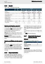
Page 26: ...IN 42955 Oscillating quantity level Level A EN 60034 14 up to the rated speed Installation altitude 0 1000 m above MSL without derating Sound pressure level MKE037 MKE1180 75 dB A 3 dB A Thermal class 155 F EN 60034 1 Encoder system A optically Singleturn Hiperface 128 signal periods B optical Singleturn EnDat 2 1 2 048 signal periods C optically Multiturn Hiperface 128 signal periods D optical Mu...

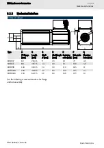
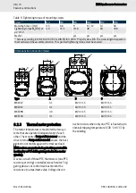
Page 27: ... ØF Type A Flange mm B Length mm C Shaft Ø mm D Shaft length mm E Centering collar mm F Hole circle mm G Mounting holes mm MKE037 60 283 5 9 20 40 70 4 5 MKE047 88 287 5 14 30 50 100 6 6 MKE098 144 383 5 24 50 110 165 11 MKE118B 194 489 5 32 60 130 215 14 MKE118D 194 662 5 32 60 130 215 14 Use the following screws and washers for flange and foot assembly ...

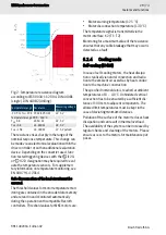
Page 28: ... 31 M20 1 5 M20 1 5 MKE047 31 M20 1 5 M20 1 5 MKE098 40 M20 1 5 M20 1 5 MKE118 41 M20 1 5 M25 1 5 6 2 3 Thermal motor protection The motor temperature is monitored by two sys tems that are operated independently of each other The mounted temperature sensor and the drive internal temperature model ensure the best protection of motors against thermal overload MKE motors are protected against impermi...

Page 29: ...he encoder data memory and are read in and monitored automatically during the operation with compatible Rexroth controllers Threshold values for MKE motors are Motor warning temperature 125 C Motor disconnection temperature 130 C The temperature signal is transmitted via the motor interface X2 T1 T2 Monitoring for a maximum value of the resistance ensures that any cable breakage that may occur is ...

Page 30: ...oint first Exception Applications where the maximum travel is within one mechanical revolution of the motor Optical encoder Multiturn absolute option C D The encoders enable absolute indirect position sensing within 4 096 mechanical revolutions The encoders replace a separate absolute value encoder at the motor The absolute axis position at this encoder variant is retained by the battery buffering...

Page 31: ...e notes about mounting drive ele ments Explosion protection When mounting drive elements check their suita bility and keep the ATEX directives during opera tion Selecting of all mounting components underlies the sole responsibility of the plant man ufacturer or operator WARNING Explosion hazard and danger to life or substan tial property damage The totality of a motor machine combination must comp...

Page 32: ...haft via axially compensating cou plings 6 2 8 Holding brake WARNING Danger to life or high damage to property igni tion and explosion hazard due to inappropriate use In order to prevent danger due to ignitable gases or explosive dust air mixtures in the vicinity of the motors the user must make sure that the holding brake does not present a source of igni tion in the normal service For this reaso...

Page 33: ...igned so as to guarantee under the worst installation and operation conditions that a suffi cient voltage 24 V DC 10 is available at the motor in order to release the holding brake The voltage drop ΔU on the brake supply can approximately be calculated for copper conduc tors using the following formula Fig 3 Voltage drop of brake supply ΔU Voltage drop V ρ Cu Specific resistance of copper Ω mm2 m ...

Page 34: ...e motor Waiting time after releasing the holding brake is at least 200 ms Decreasing the control voltage by voltage control or pulse width modulation with a PWM cycle frequency 4 kHz Decreasing the controlled voltage or PWM cycle frequency of the control voltage 4 kHz Ensure the functionality of the holding brake Remark Refer to the instructions in the con trol module documentation Refer to the no...

Page 35: ... air gap between arma ture and pole The holding brake functionality can be checked mechanically by hand or automatically by means of the software function Manually check holding torque M4 1 De energize the motor and ensure it cannot be restarted 2 Measure the transferable holding torque M4 of the holding brake with a torque wrench Check holding torque M4 using the soft ware function For Bosch Rexr...

Page 36: ...t complying with these conditions a reduced service life is to be expected Explanation of radial and axial force During operation both radial and axial forces act upon the motor shaft and the motor bearing The permissible radial force FR in distance x from the shaft shoulder and the mean speed is specified in the radial force diagrams Fig 4 Point of action of radial force FR and axial force FA The...

Page 37: ...ion limita tions Table 12 Classification limitation DIN EN IEC 60721 3 1 Bearing Ambient conditions 25 55 C Relative air humidity 5 75 Absolute air humidity 1 29 g m Direct solar radiation Not permitted Bearing Shock load Chapter 7 3 Shock load during transport und storage on page 38 Do not remove factory fitted transport protection devices such as dust protection shaft protec tion blind screw fit...

Page 38: ... e g temperature sensors encoder can contain parts sus ceptible to electrical discharge ESD Observe the ESD safety measures WARNING Risk of injury and material damage due to improper handling during transport Only use hoisting gear suited for the weight of the motors Use lifting sling belts or lifting eye bolts Secure the lifting eye bolts before use Never walk under hanging loads Never lift the m...

Page 39: ...he support is plane and the orientation is precise Avoid pinching or jamming the centering collar on the motor side Avoid damaging the receptacle fit on the plant side Use screws and washers for flange assembly according to Chapter 6 2 2 Mechanical interface on page 27 8 2 Assemble transmission elements NOTICE Motor damage due to strikes onto the motor shaft Do not strike the shaft end and do not ...

Page 40: ... circuits Secure against reactivation Ensure de energization Ground and short circuit Cover or shield any adjacent live parts WARNING High electric voltage Danger to life risk of injury by electric shock While the rotor is rotating motors with perma nent magnet excitation create a voltage 60 V at the motor connections Any work may only be carried out while the motor is at standstill Never connect ...

Page 41: ...conductor is mandatory for Ex motors according to EN IEC 60079 0 MKE Motoren must be grounded via the additional connection part protective earth terminal on the motor flange Ground terminal cross section see Chapter 8 3 7 Ground connection on page 51 Connection thermo controller The motor temperature can be evaluated via Rexroth drive controllers when MKE motors are used in potentially explosive ...

Page 42: ...42 74 MKE Synchronous Servomotors Electrical connection Bosch Rexroth AG R911402016 Edition 02 8 3 2 Wiring diagram Fig 7 Connection MKE EU with EnDat2 1 ...

Page 43: ... Bosch Rexroth AG R911402016 Edition 02 Fig 8 Connection MKE EU with Hiperface 8 3 3 Terminal boxes MKE037 E electrical connection The accessory kit SUP M04 MKE0XX is neces sary to connect the motor The accessory kit is included with the motors at delivery ...

Page 44: ... 9 Electrical connection MKE037 Housing design E 1 Remove M20 screw type blank cap and replace it by Ex cable gland 2 Remove M20 screw type blank cap and replace it by Ex cable gland 3 Tightening torque 6 3 Nm use enclosed screws 3030 Ex Ignition gap assembly damage not permis sible Notes for assembly In the case of mounting procedures flame proof gaps must be opened and jointed Avoid damages on t...

Page 45: ...osch Rexroth Fig 11 MKE X3 Pin assembly Fig 12 MKE X3 Plug in interlock Notes about assembly A hand crimping tool to handle the clamp ter minal X3 can be ordered at Bosch Rexroth Order number R911262293 Assemble the contacts within X3 connector housing as decribed in the following picture Assemble the plug in interlock 0510 on the connector housing X3 Insert the plug terminal X3 onto the printed c...

Page 46: ...llation of electrical systems Fig 13 Electric connection MKE047 housing design E 1 Remove M20 screw type blank cap and replace it by Ex cable gland 2 Remove M20 screw type blank cap and replace it by Ex cable gland 3 Tightening torque 6 3 Nm use enclosed screws 3030 Ex Ignition gap assembly damage not permis sible Notes for assembly In the case of mounting procedures flame proof gaps must be opene...

Page 47: ...g length 3 mm Crimping tool R911262293 Bosch Rexroth Fig 15 MKE X3 Pin assembly Fig 16 MKE X3 Plug in interlock Notes about assembly A hand crimping tool to handle the clamp ter minal X3 can be ordered at Bosch Rexroth Order number R911262293 Assemble the contacts within X3 connector housing as decribed in the following picture Assemble the plug in interlock 0510 on the connector housing X3 Insert...

Page 48: ...allation of electrical systems Fig 17 Electrical connection MKE098 Housing design E 1 Remove M20 screw type blank cap and replace it by Ex cable gland 2 Remove M20 screw type blank cap and replace it by Ex cable gland 3 Tightening torque 6 3 Nm use enclosed screws 3030 Ex Ignition gap assembly damage not permis sible Notes for assembly In the case of mounting procedures flame proof gaps must be op...

Page 49: ...g length 3 mm Crimping tool R911262293 Bosch Rexroth Fig 19 MKE X3 Pin assembly Fig 20 MKE X3 Plug in interlock Notes about assembly A hand crimping tool to handle the clamp ter minal X3 can be ordered at Bosch Rexroth Order number R911262293 Assemble the contacts within X3 connector housing as decribed in the following picture Assemble the plug in interlock 0510 on the connector housing X3 Insert...

Page 50: ...tion MKE118 Housing design E 1 Remove M25 screw type blank cap and replace it by Ex cable gland 2 Remove M20 screw type blank cap and replace it by Ex cable gland 3 Tightening torque 6 3 Nm use enclosed screws 3030 Ex Ignition gap assembly damage not permis sible Notes for assembly In the case of mounting procedures flame proof gaps must be opened and jointed Avoid damages on the ignition gaps Do ...

Page 51: ...th Fig 23 MKE X3 Pin assembly Fig 24 MKE X3 Plug in interlock Notes about assembly A hand crimping tool to handle the clamp ter minal X3 can be ordered at Bosch Rexroth Order number R911262293 Assemble the contacts within X3 connector housing as decribed in the following picture Assemble the plug in interlock 0510 on the connector housing X3 Insert the plug terminal X3 onto the printed circuit boa...

Page 52: ...ion against contact if neces sary Make sure that no temperature sensitive components cables electronic compo nents touch hot surfaces All persons working with motors responsible persons mechanics and planners must have knowledge skills and competence according to DIN EN 60079 14 9 2 Ambient conditions during operation Climatic conditions are defined in classes according to DIN EN IEC 60721 The cla...

Page 53: ...y Prior to commissioning ensure that the following requirements are met Ensure that the motor and all participating components of the drive are undamaged Storage time of the motor Depending on the storage time take measures to ensure safe operation Run in bearings resurface the holding brake See table Make sure that all mechanical and electrical connections temperature sensor potential equalizatio...

Page 54: ...ator Requirements on the power output stage Converter with pulse width modulation Pulse frequency 4 kHz 16 kHz Voltage load of the motor During converter operation the motor underlies a higher voltage load insulation system bearing than on a sinusoidal source voltage only Standard values for peak voltage and rate of rise of voltage Peak voltage Upk on motor clamps 1 56 kV Rate of rise of voltage d...

Page 55: ...ning Use cables with a thermal stability of at least 80 C 176 F Plug connector Never connect or disconnect plug connectors under load Operate MKE motors only with origin connec tion accessories Observe the limit values for bearing load If necessary change the bearing according to Chapter 6 2 10 Bearing on page 35 After maintenance and repair work Bosch Rexroth always recommends to do a safety and ...

Page 56: ... conductor connection at regular intervals for proper condition and tight fit and replace if necessary 10 2 Service repair mainte nance and spare parts Wearing parts are reliably and professionally repaired and replaced by the Rexroth Service in shopfloor oriented quality MKE Motoren may only be repaired at certified Bosch Rexroth service branches External service providers are not allowed to perf...

Page 57: ...zations can remain unchanged 1 If necessary note the previous absolute value 2 Open the main switch 3 Make sure the main switch cannot be switched back on 4 Disconnection plug connections Remark When exchanging the motor close open plug sides of power connec tions with protection caps if moistening with coolant lubricant or soiling must be expected allowed soiling degree according to EN 50178 2 5 ...

Page 58: ... metallic implants and hearing aids in direct environment of permanent mag nets Crushing hazard of fingers and hand due to heavy attractive forces of the magnets Risk of destruction of sensitive parts like watches credit cards Remark The permanent magnets of the rotor or secondary part must be demagnetized before disposal to avoid injuries or damage The demagnetization is reached via special therm...

Page 59: ...eturned to the country specific col lection systems for proper disposal Disposal by the manufacturer Our products can be returned to us for disposal However this requires that the products are free from oil grease or other dirt The motor compo nents must be returned in a suitable packaging origin package if possible In the case of a transport by air freight please observe the dan gerous goods regu...

Page 60: ...ns Fault description Cause Remedy Running noise Foreign bodies within the motor Stop the motor repair by manufacturer Bearing is damaged Stop the motor repair by manufacturer Fault description Cause Remedy High motor temperatures motor temperature monitoring is activated Operation outside the param eters Reduce load and check the dimensioning Heat dissipation is impaired Clean the motor As a matte...

Page 61: ...8 0 28 4 4 500 70 0 1 15 46 0 MKE118D 012 __0 _E_ 48 0 13 0 2 100 263 5 4 29 65 0 MKE118D 027 __0 _E_ 48 0 22 1 3 000 154 5 2 52 65 0 MKE118D 035 __0 _E_ 48 0 29 8 3 000 114 5 1 87 65 0 1 Manufacturing tolerance 5 14 2 Axial force Motor Symbol Unit Value MKE037 FA Nm Not permitted MKE047 FA Nm 30 MKE098 FA Nm 60 MKE118 FA Nm 200 14 3 Radial force 14 3 1 MKE037 Radial force MKE037 100 150 200 250 3...

Page 62: ... 1000 1 min n 2000 1 min n 3000 1 min n 4000 1 min n 5000 1 min Fig 29 MKE098 permissible radial force Shaft plain Shaft with keyway 14 3 4 MKE118 Radial force MKE118 500 1000 1500 2000 2500 3000 3500 4000 4500 0 10 20 30 40 50 60 x mm Fradial N n 0 1 min 25 n 0 1 min 50 n 1000 1 min n 2000 1 min n 3000 1 min n 4000 1 min n 5000 1 min Fig 30 MKE118 permissible radial force Shaft plain Shaft with k...

Page 63: ...63 74 MKE Synchronous Servomotors Specifications Bosch Rexroth AG R911402016 Edition 02 14 4 Specifications 14 4 1 MKE037 Specifications Fig 31 Specifications MKE037B ...

Page 64: ...64 74 MKE Synchronous Servomotors Specifications Bosch Rexroth AG R911402016 Edition 02 14 4 2 MKE047 Specifications Fig 32 Specifications MKE047 ...

Page 65: ...65 74 MKE Synchronous Servomotors Specifications Bosch Rexroth AG R911402016 Edition 02 14 4 3 MKE098 Specifications Fig 33 Specifications MKE098B ...

Page 66: ...66 74 MKE Synchronous Servomotors Specifications Bosch Rexroth AG R911402016 Edition 02 14 4 4 MKE118 Specifications Fig 34 Specifications MKE118 ...

Page 67: ...47 A E0 Motor types MKE047 C E0 MKE098 A E0 MKE098 B E0 MKE098 C E0 MKE098 D E0 MKE118 A E0 MKE118 B E0 MKE118 C E0 MKE118 D E0 Handelsbezeichnung Trade name Rexroth ab Herstelldatum from the date of manufacture 2021 06 01 in Übereinstimmung mit oben genannte n Richtlinie n entwickelt konstruiert und gefertigt wurden were developed designed and manufactured in compliance with the above mentioned d...

Page 68: ... Name DEKRA Testing and Certification GmbH Anschrift Address Dinnendahlstr 9 44809 Bochum Kennnummer Identification number 0158 Weitere Erläuterungen Further explanations Das Produkt ist ausschließlich zum Einbau in eine Maschine bestimmt Der bestimmungsgemässe Gebrauch des Produktes setzt die Einhaltung der Benutzungsbestimmungen und Anwendungsbedingungen die in der Betriebsanleitung angegeben we...

Page 69: ...motors China RoHS 2 Bosch Rexroth AG R911402016 Edition 02 15 3 China RoHS 2 25 The China RoHS 2 conformity can be found on the type plate of the motors Information about listing www boschrex roth com cn zh cn home_2 china_rohs2 ...
Page 70: ...22 H Helical teeth 32 Holding brake Commissioning 35 Housing temperature maximum 22 I IC410 29 IM Code EN 60034 7 36 Installation type 36 IP Code IEC 60529 30 M Maintenance 55 Motor temperature 28 O Operation on foreign converters 54 Output shaft 30 Overdetermined bearing 31 P Packaging 58 R Replace the motor 57 Residual risks 22 Returning products 59 Risk of corrosion 22 RoHS China RoHS 2 69 S Se...

Page 71: ...71 74 MKE Synchronous Servomotors Bosch Rexroth AG R911402016 Edition 02 W Warning temperature 29 Winding 31 ...

Page 72: ...72 74 MKE Synchronous Servomotors Bosch Rexroth AG R911402016 Edition 02 ...

Page 73: ...73 74 MKE Synchronous Servomotors Bosch Rexroth AG R911402016 Edition 02 ...

Page 74: ...Bosch Rexroth AG Postfach 13 57 97803 Lohr a Main Germany Bgm Dr Nebel Str 2 97816 Lohr a Main Germany Phone 49 9352 18 0 Fax 49 9352 18 8400 www boschrexroth com electrics R911402016 R911402016 ...

Reviews: