4.1.3
IndraSize
By using the IndraSize software, drive controllers, motors and mechanic
gearboxes can be easily sized. The engineering tool covers the entire range
of Rexroth drives and motors. Calculate the characteristic curves for your ap‐
plication by using the sizing and calculation tool IndraSize:
4.1.4
Characteristics
Unless otherwise specified, the values specified in the data sheets are r.m.s.
values according to DIN EN 60034-1. Reference value 540 V
DC
DC bus volt‐
age.
Behind the product-size-length-winding combination in the stator
data sheet is the cooling type.
Example: MST130C-0200-F...
“F” stands for water cooling
“N” stands for self-cooling
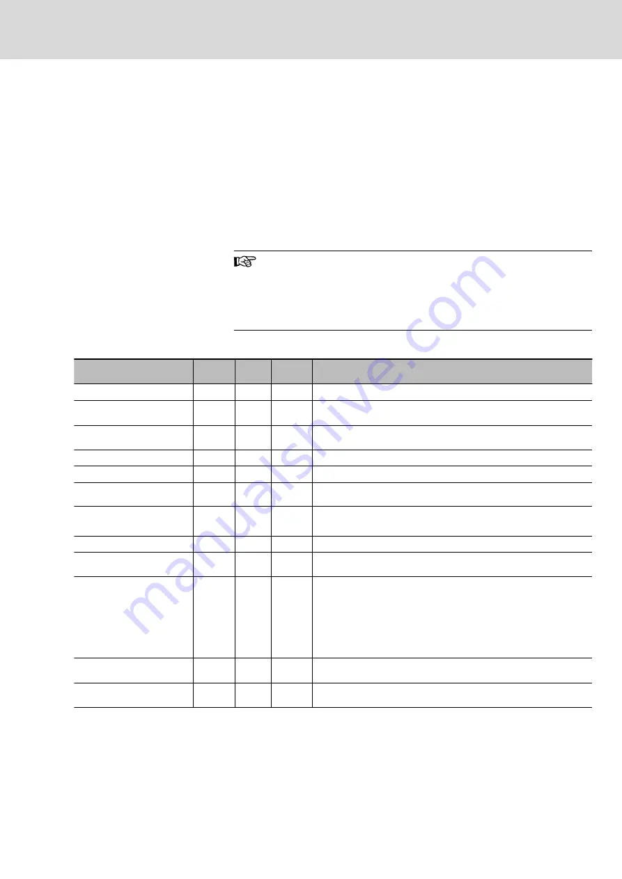
General technical data for stators MST
Designation
Symbol
Unit
Toler‐
ance
Description
Standstill torque
M
0
Nm
± 5 %
Torque for speeds n ~ 0 Hz but n > 0.1 Hz.
Standstill current
I
0
A
For standstill torque M
0
, required phase current of the motor at a speed n
> 0.1 Hz.
Rated torque
M
N
Nm
± 5 %
Available torque that can be output at the rated speed in operation mode
S1 (continuous operation).
Rated power
P
N
kW
± 5 %
Power output of the motor at rated speed and load with rated torque.
Rated current
I
N
A
Phase current of the motor at rated speed and load with rated torque.
Rated speed
n
N
min
-1
± 5 %
Useful speed defined by the manufacturer. Depending on the application,
other speeds are possible (see speed-torque characteristic curve).
Maximum torque
M
max
Nm
± 5 %
Maximum torque available at maximum current I
max
.
The achievable maximum torque depends on the drive controller used.
Maximum current
I
max
A
Maximum current (root-mean-square) of the motor at M
max
.
Maximum speed
n
max
min
-1
± 5 %
Maximum permissible speed of the motor. Normally restricted by mechan‐
ical factors such as centrifugal forces or bearing stress.
Power wire cross section
A
mm²
Rated according to DIN VDE 0298-4 and laying type B2 according to DIN
IEC 60204-1 with conversion factor for Rexroth cables at 40 °C ambient
temperature.
The power wire cross section that is specified in the data sheets can vary
depending on the selected type of connection - plug or terminal box.
When selecting the power cable, refer to the specifications in chapter
8 ”Connection technique” and the documentation ”Rexroth Connection
Cables" (DOK-CONNEC-CABLE*INDRV-AU□□-□□-P).
Torque constant
K
M_N
Nm/A
± 5 %
Ratio of generated torque M
N
to motor phase current I
N
at a winding over‐
temperature of 100 K.
Voltage constant
K
EMK_1
V/min
-1
± 5 %
Root-mean-square value of the induced motor voltage at a motor temper‐
ature of 20 °C and 1 revolution per minute.
MBT High Synchronous Torque Motors
23/409
Technical data
R911298798_Edition 08 Bosch Rexroth AG
Summary of Contents for rexroth MBT
Page 1: ...MBT High Synchronous Torque Motors Project Planning Manual R911298798 Edition 08 ...
Page 18: ...6 409 MBT High Synchronous Torque Motors Bosch Rexroth AG R911298798_Edition 08 ...
Page 32: ...20 409 MBT High Synchronous Torque Motors Bosch Rexroth AG R911298798_Edition 08 ...
Page 240: ...228 409 MBT High Synchronous Torque Motors Bosch Rexroth AG R911298798_Edition 08 ...
Page 298: ...286 409 MBT High Synchronous Torque Motors Bosch Rexroth AG R911298798_Edition 08 ...
Page 416: ...404 409 MBT High Synchronous Torque Motors Bosch Rexroth AG R911298798_Edition 08 ...
Page 421: ...Notes MBT High Synchronous Torque Motors 409 409 ...


