


5-10
Operating Instructions
IndraDynA_ATEX
DOK-MOTOR*-IDYN*A*ATEX-IB02-D5-P
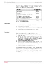
•
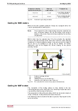
Only one of the PTC thermistor connector pairs (3-4 or 5-6)
in the motor cable should be connected to the motor; the
other one pairs serves a spare.
•
Do not remove or damage the gasket located in the lid.
•
Observe the size of the threaded cable connection and
connection thread for the cable inlet into the terminal box.
•
The connections of the motor-windings in the terminal box
must not be removed.
•
The through hole (8) in the motor housing may not be
closed or sealed off.
M
3
U
1
2
3
GN/YE
U1
V1
W1
4
3
2
1
PTC
PTC
6
5
7
8
5
6
Zu
In
Ab
Out
24V
0V
(+)
(+)
(-)
(-)
A1
A2
A3
MotTemp-
+24VBr
0VBr
1
2
3
4
5
6
7
8
9
MAx_Power_Connect_ATEX.EPS
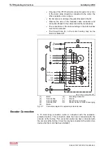
(1):
Motor
(6):
Grounding Conductor
(2):
Terminal Box
(7):
Ground
(3):
Terminal Block
(8):
Rexroth Drive Controller
(4):
Terminal Strip
(9):
Control Device for Motor Scavenging
(5):
Brake
Fig. 5-7:
Connection diagram for explosion-protected areas
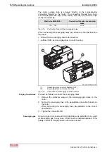
Encoder Connection
A 10 meter-long connection cable is connected with the explosion-
protected motors. This connection cable has been connected with the
encoder at the factory. This connection cable has been connected with
the encoder at the factory. It must merely be connected to the motor drive
device after the motor has been installed.