background image

6 / 52

ctrlX HMI DE0015, DE0021

Overview on target groups and product phases

Bosch Rexroth AG

R911405731, Edition 03

1

About this documentation

1.1

Change record

Table 1: Editions of this documentation

Edition Release

date

Note

01

2020-09 First edition

02

2021-02 Initial commissioning supplemented, E-STOP notes supplemented

03

2021-08 Instruction on device assembly added

1.2

Overview on target groups and product phases

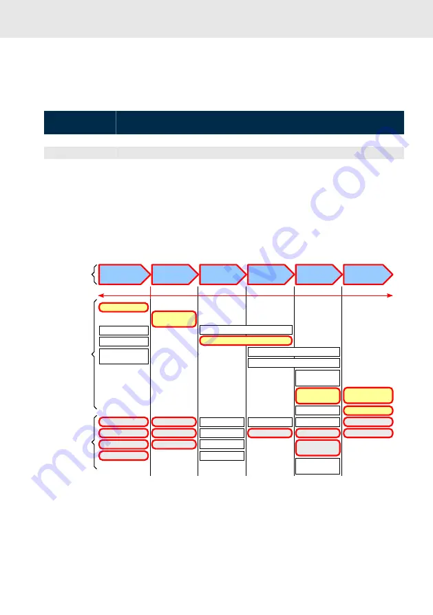
In the following illustration, the framed activities, product phases and target groups refer to the present

documentation.
Example: In the product phase “Mounting” (assembly/installation), the “Mechanic/electrician” can

execute the activity install using this documentation.

Presales Aftersales

Selection

Mounting

(assembly/installation)

Engineering

Commissioning Operation

Decommissioning

Product

phases

Target

groups

Activities

Design engineer

Programmer
Technologist

Process

specialist

Select

Prepare

Design

Construct

Mechanic/

electrician

Unpack

Mount

Install

Programmer

Commissioning engineer

Parameterize

Program

Configure

Simulate

Technologist

Process specialist

Optimize

Test

Machine

operator

Maintenance

technician

Service

Operate

Maintain
Remove

faults

Create

the NC program

Mechanic/

electrician

Disposal company

Dismount

Dispose

Fig. 1: Assigning the present documentation to the target groups, product phases and activities of the

target group
This document instructs the technical staff of the machine manufacturer on how to safely perform the

mechanical and electrical installation and on how to commission the device.

Summary of Contents for Rexroth ctrlX HMI DE0015

Page 1: ...ctrlX HMI DE0015 DE0021 Multi Touch Displays Housing Devices Operating Manual R911405731 Edition 03 ...

Page 2: ...he specified data is intended for product description purposes only and shall not be deemed to be a guaranteed characteristic unless expressly stipulated in the contract All rights are reserved with respect to the content of this documentation and the availability of the product DOK CONTRL DR DE IT03 EN P Development Automation Systems Control Platform JüFi MaKo MePe b4628c767c9b8a3e0a347e826c7d56...

Page 3: ...used 9 3 4 Explaining the signal alert symbol on the device 9 4 Intended use 10 4 1 General information on the intended use 10 4 2 Intended use of E STOP control units 10 5 Spare parts accessories and wear parts 11 5 1 External 24 V power supply unit 11 5 2 Uninterruptible power supply 11 5 3 Connecting cables for CDI interface 11 5 4 USB connecting cables USB 2 0 12 5 5 Connecting cables of the d...

Page 4: ...18 9 6 Long distance XCDI rx 18 9 7 XHDMI 18 9 8 Interface keypad 19 9 8 1 Overview 20 9 8 2 Keypad connection scheme 20 9 8 3 Pin assignment of the keypad 21 10 Mounting dismounting and electric installation 21 10 1 General information 21 10 2 Housing dimensions of the display 22 10 3 Device mounting of the display 22 10 3 1 Fastening to the support arm adapter VESA with VAS09 1 001 22 10 3 2 Fas...

Page 5: ...PCs PR31 and PR4x 38 11 3 IT security 38 12 Device description 39 12 1 General information 39 12 2 On Screen menu 40 12 2 1 Brightness 40 12 2 2 Video Input 40 12 2 3 Touch 41 12 3 Operating and error display 41 13 Error causes and troubleshooting 42 13 1 Error causes and troubleshooting 42 14 Maintenance 43 14 1 General information 43 14 2 Display 43 14 3 Cleaning notes 43 14 4 Scheduled maintena...

Page 6: ...s documentation Presales Aftersales Selection Mounting assembly installation Engineering Commissioning Operation Decommissioning Product phases Target groups Activities Design engineer Programmer Technologist Process specialist Select Prepare Design Construct Mechanic electrician Unpack Mount Install Programmer Commissioning engineer Parameterize Program Configure Simulate Technologist Process spe...

Page 7: ...uction applies to all multi touch displays whose type code starts with DE00 The type code is located on the type plate of the device also refer to 1 5 Related documentations Table 2 Related documentations Title Part number and document type Rexroth IndraControl VAP 01 Power Supply Unit R911339613 Operating Instructions Rexroth IndraControl PR and VR Devices Software Applications R911384733 Project...

Page 8: ...date MD 17W40 Name of origin Made in Company address Bosch Rexroth AG 97816 Lohr Germany CE conformity marking CE Rexroth barcode Test marking I V C B T V Voltage specification Un DC 24 V Current specification In 1 5 A Ambient temperature T amb 0 55 C Certification markings UL FCC China RoHS 2 2 Scope of delivery Multi touch display Safety instructions 24 V connection terminal E Stop connection te...

Page 9: ...ates the risk potential The signal graphics warning triangle with exclamation mark added in front of the signal words Danger Warning and Caution refer to hazards to inidividuals DANGER In case of non compliance with this safety instruction death or serious injury will occur WARNING In case of non compliance with this safety instruction death or serious injury can occur CAUTION In case of non compl...

Page 10: ...application of the operator display Handling and assembly systems Packaging and food processing machines Printing and paper converting machines Machine tools Wood processing machines The operator displays may only be operated under the mounting and installation conditions the position and the ambient conditions temperature degree of protection humidity EMC etc specified in this documentation 4 2 I...

Page 11: ... watt with RS232 interface 5 3 Connecting cables for CDI interface Malfunctions caused by using inappropriate CDI cables Use only cables listed in the following overview Table 6 Connecting cables to control cabinet PC panel PC and operator display Ordering code Part number Description RKB0008 000 5 R911171484 Length 0 5 m RKB0008 001 0 R911171485 Length 1 m RKB0008 002 5 R911170151 Length 2 5 m RK...

Page 12: ...nnecting cables of the display port The listed display port cables are provided with a special shielding The display port cables meet the following specifications Conform to the display port 1 2 Resolutions up to 4096 2160 Supports HDCP 1 3 and DPCP Table 8 Connecting cable of the display port Ordering code Part number Description RKB0063 003 0 R911391713 Connecting cable of the display port lengt...

Page 13: ... stainless steel graphite grey Square shaped mounting surface 46 mm 46 mm 1014800001 Bernstein Coupling CS 480 B Flex Square shaped mounting surface 46 mm 46 mm 5 7 Wear parts 5 7 1 General information Wear parts are not subject to any warranty 5 7 2 Backlight The service life of the backlight is limited After this period the backlight will produce only 50 of its original brightness The service li...

Page 14: ... 1 001 Power consumption 20 6 W max 32 W max Input voltage DC 24 V 25 20 DC 24 V 25 20 Operation Projected capacitive 10 point multitouchProjected capacitive 10 point multitouch Surface of the front panel Chemically strengthened front glass Chemically strengthened front glass Graphic interfaces CDI Display port HDMI CDI Display port HDMI Degree of protec tion Front panel IP 65 Front panel IP 65 US...

Page 15: ...an standards IEC 60947 1 Low voltage switchgear and controlgear Part 1 General rules IEC 60947 5 1 Low voltage switchgear and controlgear Part 5 1 Control circuit devices and switching elements Electromechanical control cir cuit devices IEC 60947 5 5 Low voltage switchgear and controlgear Part 5 5 Control circuit devices and switching elements Electrical emergency stop device with mechanical latch...

Page 16: ...tes and uses high frequency it can radiate it and it can cause harmful interferences of the wireless communication if it is not installed and used as specified in the operating instructions Harmful interferences can result if this device is operated on a residential area In this case the user has to eliminate the interferences at his own expense This device complies with part 15 of the FCC rules O...

Page 17: ...splay port plug 20 pin XHDMI Video connection to the control cabinet PC HDMI female connector type A 19 pin HDMI connector type A 19 pin XUSB USB 2 0 interfaces USB socket 4 pin type A USB plug 4 pin type A XUSBIN USB2 0 interface to the control cabinet PC USB socket 4 pin type B USB plug 4 pin type B X1S1 DC 24 V voltage supply Male connector strip 3 pin Female connector strip 3 pin NOTICE Malfun...

Page 18: ...s of the touch and the connected USB devices have to be connected to the control cabinet PC via XUSBIN When using XCDI rx these USB signals of the touch and the connected USB devices are also trans ferred A separate connection to the control cabinet PC via XUSBIN is not required 9 5 Display port XDP The display port interface XDP connects the operator display DR to the display port interface of a ...

Page 19: ...015 DE0021 Interface keypad Bosch Rexroth AG R911405731 Edition 03 9 8 Interface keypad CN1 CN2 CN4 CN3 Fig 5 USB interfaces CN1 to CN4 of the keypad S1 S2 S3 S4 Fig 6 E STOP button and pushbutton S2 S3 and S4 Interfaces ...

Page 20: ...nected acc to the connection scheme Chapter 9 8 2 Keypad connection scheme on page 20 The max load current is 500 mA 9 8 1 Overview Table 17 Keypad interfaces Name at the housing Connection type Connector type inte grated Mating connector or cable from outside CN1 Keypad connection Phönix pin contact strip 6 pin MCV 1 5 6 G 3 5 Phönix socket strip 6 pin FK MCP 1 5 6 ST 3 5 CN2 Keypad connection Ph...

Page 21: ...N C contact 1 3 S1 E STOP N C contact 2 4 S1 E STOP N C contact 2 5 S2 white N O contact N C contact 6 S2 white N O contact 7 S2 white N C contact 8 S3 black N O contact N C contact 9 S3 black N O contact 10 S3 black N C contact 10 Mounting dismounting and electric installation 10 1 General information NOTICE Mechanical damage due to incorrect mounting torque Tighten the screws and nuts with the c...

Page 22: ...7 478 270 10 3 Device mounting of the display The display is intended for a VESA compliant mounting VAS09 1 001 and for the tube mounting VAS09 1 001 For all required and matching couplings for the tube mounting refer to Chapter 5 6 Support arm adapter on page 12 10 3 1 Fastening to the support arm adapter VESA with VAS09 1 001 The DE displays are provided with four M4 treads in square arrangement...

Page 23: ...11405731 Edition 03 Mount the display as follows 1 Attach the support arm with four M4 screws at the support arm adapter 1 2 3 4 Fig 9 Support arm at adapter Support arm Adapter Marking for the alignment towards the top Four M4 screws Mounting dismounting and electric installation ...

Page 24: ...ch Rexroth AG R911405731 Edition 03 2 Screw two M5 screws into the upper bolt holes on the rear side of the device Fig 10 Two M5 screws for the support arm adapter 3 Hang the device into the support arm adapter Fig 11 Hanging the device into the support arm adapter ...

Page 25: ...nting of the display Bosch Rexroth AG R911405731 Edition 03 4 Fasten the support arm adapter in the lower bolt holes with two M5 screws 0 5 1 mm 0 5 1 mm Fig 12 Fastening the support arm adapter Mounting dismounting and electric installation ...

Page 26: ...xroth AG R911405731 Edition 03 5 Route the cables through the cable bushing of the cover and fasten the cover with four M5 screws Fig 13 Cable bushing 6 Close the cable bushing with three M5 screws Attach the routing frame to the display with two M5 screws Fig 14 Routing ...

Page 27: ... Rexroth AG R911405731 Edition 03 7 Tighten the housing cover with six M3 screws Fig 15 Tightening the housing cover 8 Remove the VESA support arm fixture from the upper mounting position and hang it into the lower screws Mounting dismounting and electric installation ...

Page 28: ...DE0015 DE0021 Device mounting of the display Bosch Rexroth AG R911405731 Edition 03 Fig 16 Rehanging the support arm adapter 9 Remove the upper screws and screw them into the lower bolt holes of the support arm adapter ...

Page 29: ...tening to an adapter for the tube mounting with VAS09 1 002 The adapter for the tube mounting is intended to be mounted at the lower housing cover If you attach the device to the adapter ensure that the screws used are suitable for the device weight Mount the adapter for the tube mounting as follows Mounting dismounting and electric installation ...

Page 30: ...sch Rexroth AG R911405731 Edition 03 1 Loosen the four screws of the plastic cover and the six M3 screws of the housing cover on the rear side of the device Fig 18 Removing the cover 2 Loosen the four M3 screws of the adapter cover Fig 19 Removing the adapter cover ...

Page 31: ...0 4 x M5 x 20 mm Rittal CP6501 050 4 x M6 x 20 mm BERNSTEIN 1014800001 4 x M6 35 x 35 46 x 46 Fig 20 Attach the adapter to the tube coupling 4 Tighten the adapter cover with four M3 screws see Fig 19 Removing the adapter cover on page 30 5 Route the connecting cable through the fixture and fasten the device with four M5 screws Fig 21 Tightening the support arm during standing mounting Mounting dis...

Page 32: ...he screen and causes additional warming The LED display on the operator panel must not be covered Wire all cables in loops Use strain reliefs for all cables To maintain the degree of protection IP 65 use only a cable bushing of the sealing gasket fitting to the cable cross sections If required use the fitting sealing gasket Do not lay the CDI cables in parallel to motor cables or to other noise so...

Page 33: ...ove the four screws of the transport cover 1 2 3 Fig 23 Opening device 10 6 2 Disassembling switch panel 1 Remove the twelve screws of the switch panel 2 Remove the two screws of the USB board 3 Remove the three screws of the board of the E STOP button 4 Remove the six screws of the pushbutton board 5 Rotate the four fastening rings to remove the pushbutton 6 Remove the three screws of the USB rub...

Page 34: ...e the six screws of the mainboard 2 Remove the four screws of the intermediate support 3 Remove the three screws of the interface cover plate 4 Remove the four screws of the connection terminal blocks of the keypad 5 Remove the four screws of the connector panel of the touchscreen 6 Remove the two screws of the connector panel of the display 1 2 3 4 5 6 Fig 25 Removing internal components ...

Page 35: ... user cannot execute any actions via the operator display during the shutdown of the control cabinet PC If the operator display is connected together with the control cabinet PC to the 24 V Out of the external UPS VAU 02 1 the user can still access the operator display during shutdown due to a power failure 10 7 2 Connecting the control cabinet PC to operator display Exemplary connection diagram o...

Page 36: ...When wiring Bosch Rexroth CDI cables with a diameter of 7 4 mm observe the following bending radii Radius when bended once while routing 4 cable diameter Minimum bending radius when moved permanently 8 cable diameter Optimum bending radius when moved permanently 12 5 cable diameter Operation breakdown due to mechanical forces on the CDI cables Avoid mechanical stress tensile compressive torsional ...

Page 37: ... is provided with the standard setting CDI connection Input rx Thus the video output and the multi touch operation are available immediately after the initial start Displayport XUSB XUSB XDP XDP USB Fig 28 Connection via standard interface After switching on the control cabinet PC and the DE display the display detects the Displayport connection and DP is shown in the lower left corner of the disp...

Page 38: ... the video and USB connection for the DE device with Displayport and USB connection set the video input via the On Screen menu on the Displayport Input DP If the video connection and the USB connection have to be modified for a DE device after a successful initial commissioning always set the new connection in the On Screen menu to ensure a correct functioning Setting up the multi touch operation ...

Page 39: ...information Bosch Rexroth AG R911405731 Edition 03 12 Device description 12 1 General information 1 2 3 4 5 6 Fig 30 Front view USB 2 0 interface i touch key Home touch key Status displays Three pushbuttons E STOP button Device description ...

Page 40: ...he menu item Brightness Brightness Brightness Video Input Exit PIP Touch 90 Exit Fig 31 On Screen menu Brightness 1 Press the Home key to open the On Screen menu 2 Press the i key to toggle to the menu item Brightness 3 Press the Home key to confirm the selection to go to the Brightness menu 4 Press the Home key to set the brightness between 0 and 100 percent 5 Press the i key to toggle to Exit 6 ...

Page 41: ...nu item Touch Brightness Always Off Video Input Off for 60 sec PIP Always On Touch Exit Exit Fig 33 On Screen menu Touch 1 Press the Home key to open the On Screen menu 2 Press the i key to toggle to the menu item Touch 3 Press the Home key to confirm the selection to go to the Touch menu 4 Press the i key to select different functionalities Always Off to disable the touch function Off for 60 sec ...

Page 42: ...splay on page 41 Table 23 Error causes and troubleshooting Error Correction No image visible Connect the supply voltage and check the X1S1 connection Connect the display port or CDI cables cor rectly If panels with display port are used use only Bosch Rexroth display cables to connect the panels refer to Distorted display due to incorrect display resolu tion Set the correct display resolution in t...

Page 43: ...klight causes a progressive deterioration display readability Thus a replacement is necessary For further information please contact the Bosch Rexroth Service 14 3 Cleaning notes NOTICE Dissolving front glass sealing with solvent Do not use solvents Do not use high pressure cleaning devices 14 4 Scheduled maintenance tasks Check all plug and terminal connections of the components for proper tightn...

Page 44: ... 15 21 5 display 16 9 21 05 Hardware Variant HW type No 1 1 06 Interface 1 3 x USB2 0 2 x host 1x device 1 07 Interface 2 Standard video DP HDMI CDI 1 08 Hardware configuration 1 IP65 ALU enclosure in Rexroth design mounting via sep VESA or pipe adapter used for pendant or pedestal support arm mounting A 09 Hardware configuration 2 Rexroth standard button module With emergency stop button 3 push b...

Page 45: ...design None NN Fig 35 Type code for VAS devices 16 Disposal 16 1 Device disassembly To prepare the disposal refer to the notes on the device disassembly Chapter 10 6 Device dismantling for disposal on page 33 16 2 Return For disposal our products can be returned free of charge However the products must be free from remains such as oil grease or other impurities Furthermore the products returned fo...

Page 46: ...kaging Bosch Rexroth AG R911405731 Edition 03 16 3 Packaging The packaging material consists of cardboard plastics wood or styrofoam Packaging material can be recycled anywhere For ecological reasons please do not return empty packages ...

Page 47: ...941 Email service svc boschrexroth de Internet http www boschrexroth com Additional information on service repair e g delivery addresses and training can be found on our internet sites Service worldwide Outside Germany please contact your local service office first For hotline numbers refer to the sales office addresses on the internet Preparing information To be able to help you more quickly and ...

Page 48: ...e 22 Disposal 33 45 Documentation Change record 6 E E STOP 15 E STOP button Service life value B10d 14 Electric installation 35 Error causes 42 Error display 41 F FCC 16 H Hazard warnings 8 HDMI 18 Helpdesk 47 Hotline 47 Housing coupling 13 Housing dimensions 22 I Identification 8 Input source video 40 Installation notes 32 Installation electric 35 Intended use 10 Interfaces 17 Keypad 19 IT securi...

Page 49: ...t symbol 9 Signal words 9 Spare parts 11 Standards 15 Support 47 Support arm adapter 12 22 Symbols 9 T Target groups 6 Technical data 14 TFT 15 Touch 41 Troubleshooting 42 U UL CSA certified 16 Uninterruptible power supply 11 UPS 11 35 USB connecting cables 12 USB interfaces 18 Use intended 10 V VESA 22 Video Input 40 Video input source 40 Voltage supply 17 35 W Warnings 8 Wear parts 11 13 X X1S1 ...

Page 50: ...50 52 ctrlX HMI DE0015 DE0021 Bosch Rexroth AG R911405731 Edition 03 ...

Page 51: ...51 52 ctrlX HMI DE0015 DE0021 Bosch Rexroth AG R911405731 Edition 03 ...

Page 52: ...Bosch Rexroth AG P O Box 13 57 97803 Lohr a Main Germany Bgm Dr Nebel Str 2 97816 Lohr a Main Germany Tel 49 9352 18 0 Fax 49 9352 18 8400 www boschrexroth com electrics R911405731 R911405731 ...

Reviews: