6 720 800 759 (2012/04)
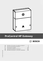
ProControl HP Gateway
Installation
|
5
en
3
Installation
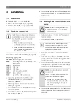
3.1 Installation
B
Remove cover (
Æ
B
Mount the module (
Æ
B
Secure the module (
Æ
3.2 Electrical connection
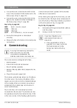
Connections and interfaces (
Æ
Key to Fig. 6, page 39:
7.5 V DC
Power supply unit connection
BUS
For configuration at the factory – do
not connect
CAN 1
Earth (GND)
CAN 2
CAN Low
CAN 3
CAN High
LAN
LAN connection (RJ45)
RESET
Reset button
TSW
Switch for CAN termination
B
Open the grommets to match the cable
diameter and make a cut on one side
(
Æ
B
Fit the grommets and connect the cables
(
Æ
B
Connect the screen of the CAN cable in the
module to CAN 1.
B
Connect one wire of the twisted wire pair in
the module to CAN 2.
B
Connect the second wire (of the twisted wire
pair used for CAN 2) in the module to CAN 3.
B
Fit the cover.
3.3 Making CAN connection to heat
pump
•
Suitable cable, 2 × 2 × 0.3 mm
2
(screened,
twisted cable).
•
The maximum cable length is 30 m.
B
Find free connections for CAN in the heat
pump.
B
If no free connection is available in the heat
pump, connect the CAN cable together with
another accessory.
B
To avoid inductive interference: Route all low
voltage cables separately from mains voltage
cables (min. clearance 100 mm).
B
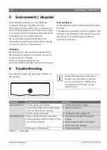
Connect the screen (earth) of the cable to the
earth connection of the heat pump (
Æ
Fig 9,
page 40).
Verify the correct position of the two
CAN termination switches to ensure
that the CAN system is correctly
terminated.
B
If the module is an end point,
both switches must be set to ON.
B
If the module is connected to a
branch cable, both switches
must be set to OFF.
NOTE:
Fault caused by interference.
B
CAN cable must be a screened,
twisted cable.
If the maximum cable length of the
CAN connection between all CAN
subscribers is exceeded, the system
cannot be commissioned.
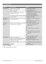
NOTE:
Do not confuse 12 V and CAN
connection!
If 12 V is connected to the CAN, the
processors will be destroyed.
B
Check that the three wires are
connected to the terminals with
the corresponding markings on
the PCB.

