English - 4
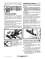
Using the Parallel/Beveling Guide
(Accessory)
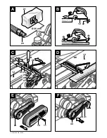
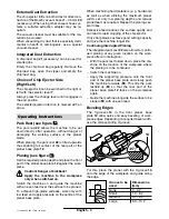
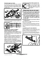
Mount parallel guide 14 or beveling guide 18 to
the machine using fastening bolt 15 and rebating
depth stop 2 using fastening bolt 1.
Loosen locking nut 16 and adjust the required re-
bating width with the scale 17. Retighten locking
nut 16 again.
Adjust the required rebating depth accordingly
with the rebating depth stop 2.
Carry out the planing procedure several times,
until the required rebating depth is reached. Pay
attention that the planer is guided with sideward
supporting pressure.
Beveling (only beveling guide 18)
When beveling rebates and
surfaces, adjust the required
slope angle with the angle
adjustment 19.
■
Before any work on the machine itself, pull
the mains plug.
■
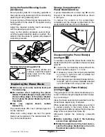
Be cautious when replacing the planer
blades: Possible danger of injury due to the
sharp cutting edges of the planer blades!
Do not grasp the planer blades by the cut-
ting edges.
■
Use only original Bosch carbide
blades (TC).
The carbide blade (TC) has 2 cutting edges and
can be reversed.
When both cutting edges are dull, the planer
blade must be replaced. The carbide blade (TC)
may not be resharpened.
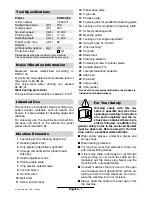
Storage Compartment for
Planer Blade/Allen Key
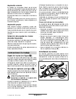
A planer blade 26 and an Allen key 28 can be
housed in the storage compartment 4 as shown
in the figure.
To remove the contents in the compartment,
completely pull the storage compartment for the
planer blade/Allen key 4 out of the planer.
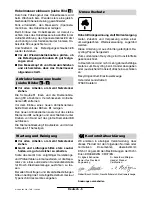
Disassembling the Planer Blade(s)
(see figure
)
To reverse or replace the planer blade, rotate the
blade drum 23 until it is parallel to the planer base
plate 12.
➊
Loosen the two fastening screws 25 with the
Allen key 28 by approx. 1 – 2 turns.
➋
If necessary, loosen the clamping element 24
by giving it a light blow with a suitable tool
(e. g. a wooden wedge).
➌
After pressing down the lateral blade-shaft pro-
tector 27, push the planer blade 26 sideward
out of the blade drum using a piece of wood.
Assembling the Planer Blade(s)
(see figure
)
The guide groove of the planer blade always en-
sures continuous height adjustment when replac-
ing or reversing it.
Clean the blade seat (clamping element) and the
planer blade respectively, if required.
When assembling the planer blade, ensure that it
is seated properly in the blade holder of the
clamping element 24 and aligned flush at the side
edge of the rear planer base plate 12.
Afterwards tighten the fastening screws 25
again.
■
Before restarting, check if the fastening
screws 25 are tightened well.
■
Rotate the blade drum 23 by hand and en-
sure that the planer blade does not run into
the planer base plate or housing.
Replacing the Planer Blade
26
28
C
D
12 • 2 609 932 233 • TMS • 12.05.03


